DHT 845
Addicted to Fun and Learning
- Joined
- Feb 28, 2021
- Messages
- 509
- Likes
- 444
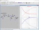
ThanksA LC filter is second order (12 dB/oct slope), and is more desirable IMHO for this application.. However, a purely LC filter will have a very high resonance peak (high Q) at the cutoff frequency, and adding a resistor into the circuit (see below, source: Wikipedia) will let you adjust the Q.
The problem is, when you plug in the numbers, a 70 Hz cutoff high pass filter will require a huge inductor, e.g. when C = 10 μF, the required L = 0.52 H, which is going to be pretty big.
so I choose LC filter, keeping coil moderate 50mH and inexpensive (ab. 6 USD) and C=100uF polypropylen cap. The coil is without core but it is made with pretty thin wire
making it quite resistive (9 Ohms). Do you think that coil resistance could "damp" the resonanse or additional damping resistor is needed. If needed I have no idea how to calculate it's value for optimal damping. Also This resistor, coil resistance and load resistance will affect effective R that preamp will see, right?


")