• WANTED: Happy members who like to discuss audio and other topics related to our interest. Desire to learn and share knowledge of science required. There are many reviews of audio hardware and expert members to help answer your questions. Click here to have your audio equipment measured for free!

ESS THD ‘Hump’ Investigation

OP
jackenhack

jackenhack

Active Member
Forum Donor
Joined
Oct 25, 2018
Messages
203
Likes
497
Location
Stockholm, Sweden
Well, reading the I2C bus on a Benchmark would be very interesting, because then we can see all the configuration registers. But I didn't think that the ESS-hump was a problem on the 9018?
My two new DAC IC's are going through Swedish customs so that I will have my Khadas board up and running next week. I'm still very curious what effect the THD compensation registers does to the measured result.
 

5th element

Member
Joined
Feb 2, 2019
Messages
42
Likes
152
Well, reading the I2C bus on a Benchmark would be very interesting, because then we can see all the configuration registers. But I didn't think that the ESS-hump was a problem on the 9018?
My two new DAC IC's are going through Swedish customs so that I will have my Khadas board up and running next week. I'm still very curious what effect the THD compensation registers does to the measured result.

I was hoping the ES9018 was immune too but somewhere in this thread someone pointed out a product that used the 9018 and also exhibited it.

When ESS first released the chips with the THD compensation it intrigued me too wondering how it would work. It is possible that you could tune things so that the hump is lessened but you make everything else around it a little worse.
 

5th element

Member
Joined
Feb 2, 2019
Messages
42
Likes
152
Thanks @pos
Seems it’s not a secret. And we can consider this issue is SOLVED.

I wouldn't necessarily say it's a completely shut case on this, remember what I've done is only a sample size of one chip, albeit through 8 channels and then pairs of them.

I am not sure if the way I proposed to use the chip would do what I'm thinking either, it would need testing. The one thing that does make sense with this idea is that some DACs under review exhibit the ESS hump, some do not, some only in one channel and some to a lesser degree than others. With the pin out of the 9018/9038 paralleling the DAC chip outputs is no trivial task, it's a lot of pins with mirroring in their configuration rather than just being a linear progression. From a designers/engineers point of view, it would make perfect sense for them to think, well I can flip the polarities of any of the DAC outputs, if that's so I'll just connect these pins together on the PCB because that wont involve such a criss-cross of PCB traces and flip the polarity later on. I did this with my layout into the 8 channels because of how everything fell into place physically.

Depending on how the designer routed their PCB you could up end with all sorts of different combinations when paralleling the DAC outputs leading to a varying amount of hump, or completely getting rid of it.
 

DonH56

Master Contributor
Technical Expert
Forum Donor
Joined
Mar 15, 2016
Messages
7,916
Likes
16,750
Location
Monument, CO
Earlier in this, or some, thread it was noted that the hump was due to lack of common-mode rejection when a proper differential circuit (or conversion) was not used. So I think the issue may be a bit overblown; it sounds like (ha ha) you just need to follow their guidance on the output buffer to eliminate the hump.

Flipping polarity may help cancel the common-mode component but may not be the best way to do it.
 

5th element

Member
Joined
Feb 2, 2019
Messages
42
Likes
152
^^^ Very interesting. Perhaps this is what @John_Siau was hinting about in the DAC3 thread without divulging their secret sauce recipe?

It could quite honestly be yeah although his description of it was a little bit condescending vs other designers. As far as I know I haven't seen a single PCB layout (from photos I've seen) that omits the opamp he implies people miss for a SE output. Although it is an easier way to say that there's some stuff you can configure in the DAC, along with a certain layout that results in the cancellation of the hump when a differential summation is used.
 

5th element

Member
Joined
Feb 2, 2019
Messages
42
Likes
152
Earlier in this, or some, thread it was noted that the hump was due to lack of common-mode rejection when a proper differential circuit (or conversion) was not used. So I think the issue may be a bit overblown; it sounds like (ha ha) you just need to follow their guidance on the output buffer to eliminate the hump.

Flipping polarity may help cancel the common-mode component but may not be the best way to do it.

Except that's exactly what almost everyone does when implementing the DAC, follows the datasheets recommendation for after DAC circuitry. It's a fairly common circuit that all differential current output DACs use, except it does not cancel out the hump issue. This requires you flip the polarity of another SE output channel, pair it with an un-flipped and sum them again. Which is not in the data-sheet.
 

DonH56

Master Contributor
Technical Expert
Forum Donor
Joined
Mar 15, 2016
Messages
7,916
Likes
16,750
Location
Monument, CO
Except that's exactly what almost everyone does when implementing the DAC, follows the datasheets recommendation for after DAC circuitry. It's a fairly common circuit that all differential current output DACs use, except it does not cancel out the hump issue. This requires you flip the polarity of another SE output channel, pair it with an un-flipped and sum them again. Which is not in the data-sheet.

I don't have the datasheet so have no reason to doubt you. I am working (again, on Sunday :( ) and missed the situation, sorry. Now I see the issue. ESS has historically been secretive about providing them without and NDA, and several years ago when I asked they refused to even send me the NDA form as I was (and am) not an audio manufacturer. Hopefully that has changed.

Is that why so many use multiple channel DACs to produce stereo output? Curious, not challenging... The differential-to-single-ended conversion should cancel CM distortion so long as it did not generate differential distortion as well (common-mode modulation often leads to adding differential mode errors as well as common-mode, at least at the transistor level). Seems like the extra operation is to compensate the differential as well as common-mode distortion components. I tried something similar a long time ago but in that case the added noise and distortion was more than if I simply beefed up the primary output circuit to provide better performance unless I really burned some power. That was at RF, however, and in a power-sensitive application instead of an audio box for your desk or rack.

Thanks - Don
 

Bartman

New Member
Joined
Feb 3, 2019
Messages
2
Likes
2
Hallo everyboby,
i'm new forumer of this wonderful site, i find it searching infos about SMSL SU-8 DAC.
First of all i would like to thank amirm and all his collegue for the work they did, do and will do for us, audio equipment enthusiasts!
I'm not a technician so i have a question about ESS 9038 hump: how can this behavior affect the sound of the dac ?
Thank you in advance for your replies.
 

RayDunzl

Grand Contributor
Central Scrutinizer
Joined
Mar 9, 2016
Messages
13,250
Likes
17,203
Location
Riverview FL
how can this behavior affect the sound of the dac ?

Likely inaudible, there may be an extreme case where it is heard.

If I read the graph correctly, it occurs about 65 to 90dB below the signal, but when the signal has already been attenuated by 20 to 40dB.

That's way down there, so to speak, in practical terms.

1549211385228.png
 
Last edited:

5th element

Member
Joined
Feb 2, 2019
Messages
42
Likes
152
Likely inaudible, there may be an extreme case where it is heard.

If I read the graph correctly, it occurs about 65 to 90dB below the signal, but when the signal has already been attenuated by 20 to 40dB.

That's way down there, so to speak, in practical terms.

Right after you've applied 20-40dB of digital attenuation the distortion rises. Yes the distortion is low down in level but I do find it a bit of a problem, at least from a technical point of view.

With the ESS chips you are directly paying for their technical performance. 20 to 40dB down is a very important range. Most of the DAC/headphone amps under review use digital attenuation and RE a 2VRMS SE output at 0dBfs most people will be setting their volume control to -20-40dB for a lot of their listening, bang in the range where you want the highest DAC linearity, not the ESS hump to be present.
 

gvl

Major Contributor
Joined
Mar 16, 2018
Messages
3,510
Likes
4,093
Location
SoCal
Is the hump present with both external and internal attenuation? I thought Amir tests using the former.
 

Zoide

Active Member
Joined
Oct 20, 2018
Messages
100
Likes
75
Is the hump present with both external and internal attenuation? I thought Amir tests using the former.
I was about to ask a related question:

Is the hump absent for those of us who run the DAC at full digital volume and control the volume via an external headphone amp's potentiometer?
 

Bartman

New Member
Joined
Feb 3, 2019
Messages
2
Likes
2
Right after you've applied 20-40dB of digital attenuation the distortion rises. Yes the distortion is low down in level but I do find it a bit of a problem, at least from a technical point of view.

With the ESS chips you are directly paying for their technical performance. 20 to 40dB down is a very important range. Most of the DAC/headphone amps under review use digital attenuation and RE a 2VRMS SE output at 0dBfs most people will be setting their volume control to -20-40dB for a lot of their listening, bang in the range where you want the highest DAC linearity, not the ESS hump to be present.

I would like to buy SMSL SU-8 to drive in balanced an Advance Acoustic MAA406.
Not seams a good idea...
 

RayDunzl

Grand Contributor
Central Scrutinizer
Joined
Mar 9, 2016
Messages
13,250
Likes
17,203
Location
Riverview FL
Is the hump absent for those of us who run the DAC at full digital volume and control the volume via an external headphone amp's potentiometer?


As I might interpret the measurement, the distortion occurs when the input signal level crosses the area of problematic amplitude.

The DAC's volume control is not being exercised above, the level is controlled by the AP's test signal level.

As the signal level crosses the area of -65 to -90dB there is "some" distortion of the output during the portion of the signal in those areas.

A signal with a peak below -90dB is not disturbed.
A signal with a peak from -90 to -65dB has its top part disturbed.
A signal with a peak greater than -65dB has a disturbance in the area of -90 to -65dB (middle vertical part of the wave) as the waveform evolves.

Maybe.
 
Last edited:

Krunok

Major Contributor
Joined
Mar 25, 2018
Messages
4,600
Likes
3,069
Location
Zg, Cro
I was about to ask a related question:

Is the hump absent for those of us who run the DAC at full digital volume and control the volume via an external headphone amp's potentiometer?

My guess is that it's level dependent so it's present no metter how you control the volume.
 

amirm

Founder/Admin
Staff Member
CFO (Chief Fun Officer)
Joined
Feb 13, 2016
Messages
44,724
Likes
241,674
Location
Seattle Area
Is the hump absent for those of us who run the DAC at full digital volume and control the volume via an external headphone amp's potentiometer?
No. The IMD test is varying the digital sample values so that is what matters, not what analog output you are using.
 

thunderchicken

Active Member
Joined
Feb 5, 2019
Messages
152
Likes
150
Location
Seattle
I keep seeing "ESS Hump" and the graphs showing the hump, but I'm confused as to the effect. Does the hump mean that signals in the middle of a program's dynamic range are more distorted? Or does it mean that with a Sabre DAC we need to keep the level control as high as possible to get the best SINAD performance?

Edit: Looks like I'm not the only one confused on this point :)
 

amirm

Founder/Admin
Staff Member
CFO (Chief Fun Officer)
Joined
Feb 13, 2016
Messages
44,724
Likes
241,674
Location
Seattle Area
Distortion is generated as digital values traverse a range of values in the middle. There is no work-around that I can think of. You could probably make things worse by lowering the volume ahead of the DAC (e.g. software volume control). So best to leave software levels at 100% and then reduce the volume in the DAC or pre-amplifier.
 

hetzer

Member
Joined
Nov 24, 2018
Messages
45
Likes
121
I found a new clue explaining the hump. This information is from TI and related to newest mobile DAC chip. I tried to expain it as simple as possible, but it is still a long story.
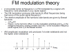
Majority of modern audio DAC chip has multi-bit delta-sigma architecture to achieve lower out-of-band noise and robustness to jitter. But 'multi-bit' means that there is an issue about element mismatch just as R2R DACs. So several manufacturers like ESS uses DEM(Dynamic Element Matching) to send the distortion by element mismatch to ultrasonic frequency.
2.PNG

DEM is implemented by using a splitter between modulator and dac. The spltter distributes the signal to each 1bit dac(a switch) in a certain pattern. This pattern can be random, DWA(Data Weighted Algorithm) or modified DWA. The most common method and what ESS use is barrel-shifting DWA. This link will describe it with pictures.

However, barrel-shifting DWA has problem with 'tone' that is created by itself. The following presentation is a part of 
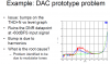
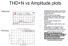
A 110dB SNR and 0.5mW Current Steering Audio DAC in 45nm CMOS from TI
ti 1.PNG

ti 2.PNG

ti 3.PNG

ti 4.PNG

ti 5.PNG

ti 6.PNG

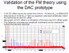
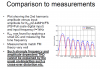
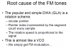
In this presentation, the root cause of THD hump is said to be a tone behaviour of DWA. This is the most powerful scientific explanation of 'hump' I know. Even though ESS notched the tone out as shown on the presentation above, it basically don't fix the drawback of DWA and it can still cause problems. A white paper from Wolfson(link) supports this theory. This paper criticizes simple barrel-shifting DEM that 'since the error is only shaped by a first order function, there are similar concerns as for first order delta-sigma modulators - in particular the presence of in-band tones for small DC offsets.' 'A small dc offset causes the element selection pattern to slowly rotate and with a component mismatch a low frequency tone can occur in standard rotating DEM scheme.'

But this can't explain the exceptional cases like Benchmark DAC3, Melokin DA9.1 and Topping NX4. Furthermore, the previous resource from ESS that I used to explain THD hump(link) boasts the improvement of their SabrePRO that they added dither on quantizer and improved DEM algorithm. However, as many DACs with SabrePRO chip still suffer from the hump, PRO versions may not have solved the issue.

In my personal opinion, ESS DAC is more sensitive to DC offset than other DAC chips because of DEM issue. But just as John Siau said, if the output circuit is carefully designed with well-trimmed differential amplifier and cancel out the distortion precisely, the hump can be abbreviated. This is practical theory that can explain most of the measurements. But I don't know exactly why is it sensitive to DC offset and why it can be fixed.

To conclude, nothing is clear and we need more measurements and data unless ESS gives us information.
 

Attachments

  • ti 1.PNG
    ti 1.PNG
    54 KB · Views: 317
  • ti 2.PNG
    ti 2.PNG
    59.9 KB · Views: 126
  • ti 3.PNG
    ti 3.PNG
    81.9 KB · Views: 168
  • ti 4.PNG
    ti 4.PNG
    75.1 KB · Views: 278
  • ti 5.PNG
    ti 5.PNG
    77.7 KB · Views: 252
  • ti 6.PNG
    ti 6.PNG
    42.6 KB · Views: 120

DonH56

Master Contributor
Technical Expert
Forum Donor
Joined
Mar 15, 2016
Messages
7,916
Likes
16,750
Location
Monument, CO
Tones due to static signals are described in every introductory text on delta-sigma converters. DC offsets caused significant tones in the earliest designs (low-order, single-bit). Higher-order loops, dither (noise decorrelation), and multibit designs pretty much killed them many years ago. But it seems like the DEM schemes used to improve the multibit converters has brought this old problem back. Ironically back in the mid-1990's I was designing a DAC and considered DEM. I scrapped it mainly due to power and voltage headroom issues, but did see the modulation described in the slides when I used a simple shifter. I had totally forgotten about that. I went to a PRNS (pseudo-random noise source) and that squelched the tones.

I have some old notes for a college class I gave on DS converters but when I tried to resurrect the notes a couple of years ago I failed. It was in AmiPro; MS Office had but no longer has a converter, and a comercial converter got the text but not the figures -- and it was pretty much all figures! Blah. It had a few slides on tones with pretty pictures. Including Bessel functions, not one of my most favorite things... They are also used in the derivation of SFDR for an ideal converter.
 
Top Bottom