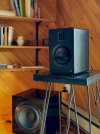
-
Welcome to ASR. There are many reviews of audio hardware and expert members to help answer your questions. Click here to have your audio equipment measured for free!
You are using an out of date browser. It may not display this or other websites correctly.
You should upgrade or use an alternative browser.
You should upgrade or use an alternative browser.
DIY speaker stands
- Thread starter CPTX
- Start date
Not bad, but do make sure that the hardware is rated to take more than the full weight of the speakers. The VIVO stands I'm using are rated for a screen that weighs more than the Genelecs, but it was quite hard to get them to stay straight, I had to use a lot of muscle to tighten the bolt. I think this is because the weight distribution of a speaker is much further from the hinge than a screen's, so the torque ends up being a lot higher.
The stands arrived this morning. They are very sturdy as they are designed to handle 2x 10KG. There is enough space on the platform that the VESA plate mates to, to drill a hole for the 3/8" screw that came with the MTMs. I will probably put a foam pad or spacer between the platform and the bottom of the MTM.
Drilling the hole won't affect the arms original function, i'll still be able to use it with the VESA plate later if I want to.
I'm also hoping I can use the rear mounting hole on the MTMs, this will allow me to tilt the mounting plate down and hide the arm behind the MTM a little...
I will post more pictures when the desk is built and everything is installed.
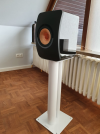
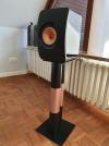
That is soooo OCD... maybe we should both seek therapy!In the past I had spray painted my loudspeaker stands to colour match them to my LS50, before
View attachment 369831
and after
View attachment 369832
Drilling the hole won't affect the arms original function, i'll still be able to use it with the VESA plate later if I want to.
I don't mean to meddle: Can you make metal, curved bracket over those 2 screw-inserts w/an oblong hole in the center?
You can probably get enough of a bite to slide unit up- and-down by about 3 cm.
Sounds like a cheap fix but I may be looking at your photos/problem down-and-up!
View attachment 369905
I don't mean to meddle: Can you make metal, curved bracket over those 2 screw-inserts w/an oblong hole in the center?
You can probably get enough of a bite to slide unit up- and-down by about 3 cm.
Sounds like a cheap fix but I may be looking at your photos/problem down-and-up!
I'm not sure what you mean. The inserts are on the bottom of the MTM, the screw will go up through the hole i'll drill in the bracket and into one of the inserts, so the MTM will sit directly on the end of the monitor arm, like this...
My suggestion was to make a (2cm or 3cm) piece of metal inserted between the arm and the speaker's pick-up screw mounting holes.
Using the middle oblong cut-out in the center of this piece of metal may allow you some additional tilting capability of the speaker.

/\ /\ Something like this /\ /\
That short mounting screw may have to be replaced and and its head would have to be inside that recessed oblong cut-out in the middle of the metal insert.
You certainly did not think that I was going provide you with an accurate (+time consuming) CAD drawing, for the metal insert... did you???
Using the middle oblong cut-out in the center of this piece of metal may allow you some additional tilting capability of the speaker.
/\ /\ Something like this /\ /\
That short mounting screw may have to be replaced and and its head would have to be inside that recessed oblong cut-out in the middle of the metal insert.
You certainly did not think that I was going provide you with an accurate (+time consuming) CAD drawing, for the metal insert... did you???
Last edited:
My suggestion was to make a (2cm or 3cm) piece of metal inserted between the arm and the speaker's pick-up screw mounting holes.
Using the middle oblong cut-out in the center of this piece of metal may allow you some additional tilting capability of the speaker.
View attachment 369996
/\ /\ Something like this /\ /\
That short mounting screw may have to be replaced and and its head would have to be inside that recessed oblong cut-out in the middle of the metal insert.
You certainly did not think that I was going provide you with an accurate (+time consuming) CAD drawing, for the metal insert... did you???
I understood what you were describing, but I failed to understand why you thought it was necessary. The plate on the end of the monitor arm is articulated and has almost 180 degrees of adjustment in the same plane as your plate would provide.
In any case, i've had to revise my plans slightly. The 3/8" screws that came with the MTMs (for use with their desk stands) have very large heads which are a tight fit in the space I indicated with the blue arrow.
Plan A - I've ordered some new 3/8-16 - 1/2 screws with socket heads of a much smaller diameter. I should add that I grew up with the metric system; so working out exactly what imperial size I needed was a little confusing. It's also more difficult and expensive to source imperial screws in the UK and the screws need an imperial Allen key (although there will probably be a close enough metric equivalent).
Plan B - I've also ordered some 3/8" male to M8 female adapters. I will attach these to the end of the monitor arm with some M8 socket head screws which I already have. This solution has a couple of benefits; M8 is smaller diameter than 3/8", so a smaller hole is required in the mounting plate and I can use the metric Allen key, supplied with the arm, to tighten it. My concern with this approach is the 'Aluminum Alloy' the adapter is made of, it might not be sturdy enough to hold the MTM securely. I've not managed to find the same adapter in steel (or brass) yet.
Update - I had to go with Plan A - the 3/8 thread on the M8 adapter is too short and only screws into the base of the MTM by 1 or 2 threads. It actually feels pretty solid, but i'm not going to risk it.
I drilled the hole out to 9.5mm, used my Dremmel to make enough room for the larger socket head on the 3/8 screw. It's looks good and the stand is rock solid...


I drilled the hole out to 9.5mm, used my Dremmel to make enough room for the larger socket head on the 3/8 screw. It's looks good and the stand is rock solid...
Doenerkunde
Active Member
- Joined
- Dec 29, 2022
- Messages
- 175
- Likes
- 453
My speaker stands consist of a pair of 50€ Amazon barstools without the seat attached. They are made from stamped steel, so they would ring, but I sealed them with black rough duct tape and black silicone and filled them with sand. They are very quiet now, no more obvious ringing. I used black door seals for the top and cable ties to fix the speaker cables to the stands.
The barstools I used: https://www.amazon.de/gp/product/B083B9ZCWP/
This is the outcome, I like it very much:
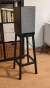
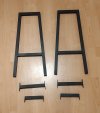
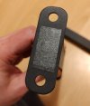
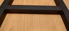
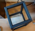
The barstools I used: https://www.amazon.de/gp/product/B083B9ZCWP/
This is the outcome, I like it very much:


That's clever, sturdy and economical. And, I should mention easy with probably many options and looks. Outside the box, Sir. VG++My speaker stands consist of a pair of 50€ Amazon barstools without the seat attached. They are made from stamped steel, so they would ring, but I sealed them with black rough duct tape and black silicone and filled them with sand. They are very quiet now, no more obvious ringing. I used black door seals for the top and cable ties to fix the speaker cables to the stands.
The barstools I used: https://www.amazon.de/gp/product/B083B9ZCWP/
This is the outcome, I like it very much:
View attachment 370408View attachment 370409View attachment 370410View attachment 370411View attachment 370412
Dave Bullet
Member
- Joined
- Oct 30, 2022
- Messages
- 96
- Likes
- 117
Cool idea. Here's my recent attempt (before sanding and varnishing) then finished and speaker on top (speaker has a rebated bottom). Timber is Garapa (hardwood). Left over from a deck build


I looked at that ?Garapa? wood in the nude (top photo) and thought it must be like that "Rubberwood" that comes-out real sh*tty when stained!Timber is Garapa (hardwood).
I scrolled a bit down and -- omg -- she looks so much better stained (acacia+oak like). Congrats!
Trying to match grains (from multiple/different trees) for some woods just doesn't come out uniform upon staining.
Last edited:
Dave Bullet
Member
- Joined
- Oct 30, 2022
- Messages
- 96
- Likes
- 117
I just applied clear varnish. Garapa is naturally honey coloured I suppose. I didn't bother grain matching etc... I just used left over bits the right size.I looked at that ?Garapa? wood in the nude (top photo) and thought it must be like that "Rubberwood" that comes-out real sh*tty when stained!
I scrolled a bit down and -- omg -- she looks so much better stained (acacia+oak like). Congrats!
Trying to match grains (from multiple/different trees) for some woods just doesn't come out uniform upon staining.
Hey nice. Make some tops and print some parts you might have a business there. Offer with/without pipes and three heights. Ipe needs some finish IMHO. Good job
... and we all know that some OCD customer is going to ask you for a...Hey nice. Make some tops and print some parts you might have a business there. Offer with/without pipes and three heights. Ipe needs some finish IMHO. Good job
... custom color.... which will mean that you also have to staff-up a CustomerService department...
Oy!
What do you do when it rains again for days on end ...
You might be thinking about the past, when everything was nice. And that's what I do now too:
Speaker stand with SCHUBIDU. SCHUBIDU was born in Berlin - a permanent loan from my daughter.

The pipe only looks thinner because of the flash at the top.
My self-made, very simple speaker stand:
Built in one afternoon (2004) with parts I had in my garage. And because of the thread topic I show you the details for DIY:
Neumann KH310 (since 2016):
Place the cork board underneath so that the KH310 rests absolutely firmly on the upper wooden board.
All feet of the speaker stand must have firm contact with the floor. Feel it with your index finger when you try to wiggle the stand.
Check this after a few weeks.
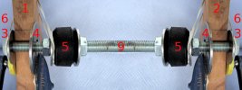
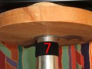
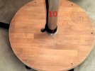
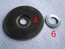
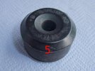
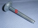
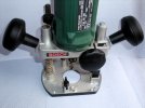
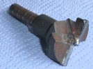
Parts of the speaker stand:
P1: Upper wooden disc (glued wood panel beech 28 x 250 mm)
P2: Lower wooden disc (glued wood panel beech 28 x 460 mm)
P3: Small washers with spring washers (P6) and nuts
P4: Large washers at the ends of the pipe (P10)
P5: Rubbers in the pipe (P10) for centring and fastening the threaded rod (P9) with nuts
P6: 2 to 3 spring washers on each side
P7: Velcro tape
P8: Adjustable feet (the thread is cut into the wooden disc (P2))
P9: Threaded rod D 12 mm
P10: Pipe (stainless steel D 48 x 2 mm)
For P1/P2:
Are created with the wood router in several steps. The parallel guide of the wood router was extended with two threaded rods.
Use a drill stand that stands on the glued wood panels so that the holes are drilled at an angle of 90°.
I had the least waste with the dimensions mentioned above.
If the gluing is of poor quality, individual wood segments can break out.
For P3:
Use a router to mill the blind hole at the top so that (P3) does not protrude.
For P4:
The pipe are fastened between these washers with (P3).
Centring during assembly: only by hand / with adhesive tape / with a suitable washer
For P5:
Were spare parts for an old Mercedes car of mine. First attach the lower rubber with the nuts, fill the pipe with fine dry sand and then attach the upper rubber. The two inner nuts (left and right of (P9)) must of course be secured with one nut each.
For P8:
The length of the feet determines whether you can still work under the glued beech panel with a hoover.
I could also remove dust again ...
Should be painted black - been on my to-do list intermittently since 2004 ...
Alternatives for hard floors: e.g. Allen screws: Allen to the floor and with a saw slot for screwdrivers, ...
For P10:
Precise 90° cut if you don't have a machine for this (like me): e.g. wrap a sheet of photocopy paper around the pipe at the desired position so that all layers of paper are on top of each other. Cut the pipe with a diamond disc at a distance of at least approx. 0.5 mm from the paper. The easiest way is for a helper to turn the pipe slowly on a slightly open vice.
Neumann KH310 - Resonances of the grille:

The resonances of the metal grilles can be measured and heard when the grille is struck with an object. The resonances are audibly and measurably reduced with a few magnets in the area of the bass loudspeaker. The magnet must not be too thick so that the bass speaker does not strike.
Additional magnets on the other side would reduce the resonances even further, but this would lead to reflections (which have not yet been measured).
SCHUBIDU is happy that it is not raining.

You might be thinking about the past, when everything was nice. And that's what I do now too:
Speaker stand with SCHUBIDU. SCHUBIDU was born in Berlin - a permanent loan from my daughter.
The pipe only looks thinner because of the flash at the top.
My self-made, very simple speaker stand:
Built in one afternoon (2004) with parts I had in my garage. And because of the thread topic I show you the details for DIY:
Neumann KH310 (since 2016):
Place the cork board underneath so that the KH310 rests absolutely firmly on the upper wooden board.
All feet of the speaker stand must have firm contact with the floor. Feel it with your index finger when you try to wiggle the stand.
Check this after a few weeks.


Parts of the speaker stand:
P1: Upper wooden disc (glued wood panel beech 28 x 250 mm)
P2: Lower wooden disc (glued wood panel beech 28 x 460 mm)
P3: Small washers with spring washers (P6) and nuts
P4: Large washers at the ends of the pipe (P10)
P5: Rubbers in the pipe (P10) for centring and fastening the threaded rod (P9) with nuts
P6: 2 to 3 spring washers on each side
P7: Velcro tape
P8: Adjustable feet (the thread is cut into the wooden disc (P2))
P9: Threaded rod D 12 mm
P10: Pipe (stainless steel D 48 x 2 mm)
For P1/P2:
Are created with the wood router in several steps. The parallel guide of the wood router was extended with two threaded rods.
Use a drill stand that stands on the glued wood panels so that the holes are drilled at an angle of 90°.
I had the least waste with the dimensions mentioned above.
If the gluing is of poor quality, individual wood segments can break out.
For P3:
Use a router to mill the blind hole at the top so that (P3) does not protrude.
For P4:
The pipe are fastened between these washers with (P3).
Centring during assembly: only by hand / with adhesive tape / with a suitable washer
For P5:
Were spare parts for an old Mercedes car of mine. First attach the lower rubber with the nuts, fill the pipe with fine dry sand and then attach the upper rubber. The two inner nuts (left and right of (P9)) must of course be secured with one nut each.
For P8:
The length of the feet determines whether you can still work under the glued beech panel with a hoover.
I could also remove dust again ...
Should be painted black - been on my to-do list intermittently since 2004 ...
Alternatives for hard floors: e.g. Allen screws: Allen to the floor and with a saw slot for screwdrivers, ...
For P10:
Precise 90° cut if you don't have a machine for this (like me): e.g. wrap a sheet of photocopy paper around the pipe at the desired position so that all layers of paper are on top of each other. Cut the pipe with a diamond disc at a distance of at least approx. 0.5 mm from the paper. The easiest way is for a helper to turn the pipe slowly on a slightly open vice.
Neumann KH310 - Resonances of the grille:

The resonances of the metal grilles can be measured and heard when the grille is struck with an object. The resonances are audibly and measurably reduced with a few magnets in the area of the bass loudspeaker. The magnet must not be too thick so that the bass speaker does not strike.
Additional magnets on the other side would reduce the resonances even further, but this would lead to reflections (which have not yet been measured).
SCHUBIDU is happy that it is not raining.

Similar threads
- Replies
- 1
- Views
- 977
- Replies
- 2
- Views
- 875
- Replies
- 12
- Views
- 1K
