• WANTED: Happy members who like to discuss audio and other topics related to our interest. Desire to learn and share knowledge of science required. There are many reviews of audio hardware and expert members to help answer your questions. Click here to have your audio equipment measured for free!

DIY Built: Cheap Trick 6 Channel TPA 3255 PBTL

yo!

Member
Joined
Oct 2, 2024
Messages
45
Likes
51
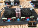
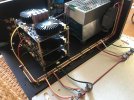
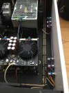
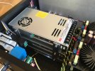
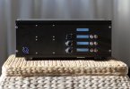
Finished a DIY project over Xmas.
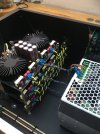
It's a 6 channel TPA3255 in PBTL. It was designed as a low cost built and the financial limit was 600 bucks, as this is the amount I gained by selling some electronic stuff.

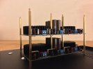
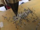
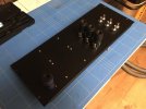
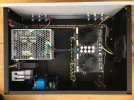
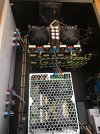
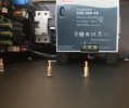
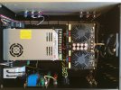
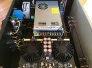
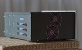
Not much to say about it, just modded the boards a bit and put them with a 48V 20 A SMPS into a acceptable case.
Finished weight is about 11.3 kg, StandBy consumption <0.5W. Everything works flawless. In simple stereo mode @ 6 ohm fullrange speakers there's already enough power for my needs, not to mention 3 way active config with double bass @3 ohm when PBTL delievers plenty current.
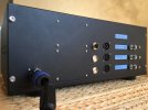
Included:
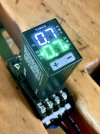
auto start module (-58 dB signal on)
FI protect
programmable timer (anti popp)
main soft start
5V sec. SMPS
primary EMI filtering for each SMPS
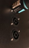
Neutrik connectors
silent fans (optional for hot summer days)

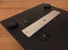
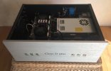
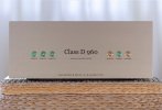
Some pics of the built, not only for the Ego but for inspiration, as I got inspired by some forum postings too. :)
 

Attachments

  • asr 960 Front Final s.jpg
    asr 960 Front Final s.jpg
    196.2 KB · Views: 173
  • asr 960 Back Final s.jpg
    asr 960 Back Final s.jpg
    178.4 KB · Views: 168
  • asr 960 Side Final s.jpg
    asr 960 Side Final s.jpg
    260.8 KB · Views: 165
Last edited:
part 2/3
 

Attachments

  • asr timer II.jpg
    asr timer II.jpg
    251.6 KB · Views: 122
  • asr stack.jpg
    asr stack.jpg
    238.1 KB · Views: 132
  • asr chunk.jpg
    asr chunk.jpg
    303.1 KB · Views: 121
  • asr tree.jpg
    asr tree.jpg
    182.5 KB · Views: 122
  • asr back II.jpg
    asr back II.jpg
    180.8 KB · Views: 133
  • asr pimp.jpg
    asr pimp.jpg
    336.7 KB · Views: 128
  • asr stiffy.jpg
    asr stiffy.jpg
    224.6 KB · Views: 134
Last edited:
part 3/3
 

Attachments

  • asr chip.jpg
    asr chip.jpg
    181.8 KB · Views: 131
  • asr speakon.jpg
    asr speakon.jpg
    135.1 KB · Views: 121
  • asr timer.jpg
    asr timer.jpg
    193.4 KB · Views: 131
  • asr wiring IV.jpg
    asr wiring IV.jpg
    335.6 KB · Views: 130
  • asr wiring.jpg
    asr wiring.jpg
    292 KB · Views: 134
  • asr wiring III.jpg
    asr wiring III.jpg
    299.7 KB · Views: 142
  • asr wiring II.jpg
    asr wiring II.jpg
    247.4 KB · Views: 153
  • asr wiring I.jpg
    asr wiring I.jpg
    264.9 KB · Views: 139
  • asr smps.jpg
    asr smps.jpg
    211.2 KB · Views: 136
Last edited:
really cool ! so at the moment it is set up as a 3 channel amp ? with each board operating in bridged mode ? is that correct . some other questions where did you buy the boards and In your first set of photos there are loads of capacitors have you replaced all the capacitors on the amplifier boards with a more reliable type ? or are you using them for some other purpose ?
kind regards James
 
Hi James,

these are the boards you find on ali sold by aiyima and others, when on sale they're a no brainer. Micheal Beene gave them a thumbs up in his review (identical boards with slightly different heatsinks). The amp is configured as a 6 channel amp, every speakon connector has 2 outputs. It's a flexible solution for stereo only or in combination with a miniDSP up to 2x3 channels active.
The caps got changed for higher capacity and lower ESR plus higher voltage rating (50 vs. 63 V). The ChemiCon types are nice ones and 4000 uF per chip is matching the Ti reference specs pretty good. I set the DC voltage to 46.5 V anyway to run the boards as cool as possible.

The MnZn coils are much higher rated as the former ironpowder toroidals and pass 10A before they're hit saturation. Changed the 1uF output filter caps for 0.68 to get a lower Q that fits better with most tweeters and offer a smoother roll off.
I also cleaned the thermal paste mess.

There could be much more done in terms of optimizing, but to me it's all right and the most obvious shortcommings has been solved now. For sure you can use the modules as they come too.

Greets!
 
Last edited:
Finally ... I ran into a major problem! :)

Till now I used the amp for 2 channel stereo, and it worked flawless all the time.
But when I tried the multi channel setup, it was game over. It seems, those modules don't like to work with a shared SMPS. Somehow they start to interfere with each other and a loud whistling noise kicks in.
Not sure what's the reason for this behavior, checked some usual causes like grounding issues, separated the auto start module and unplugged some connections, but found no flaw in the layout. Even the power supply is floating ... no clue why the PBTL boards are this problematic when they share a SMPS.

The only solution seems to offer each module it's own power supply. hm ....
 
Last edited:
Finally ... I ran into a major problem! :)

Till now I used the amp for 2 channel stereo, and it worked flawless all the time.
But when I tried the multi channel setup, it was game over. It seems, those modules don't like to work with a shared SMPS. Somehow they start to interfere with each other and a loud whistling noise kicks in.
Not sure what's the reason for this behavior, checked some usual causes like grounding issues, separated the auto start module and unplugged some connections, but found no flaw in the layout. Even the power supply is floating ... no idea, why the PBTL boards are this problematic when they share a SMPS.

The only solution seems to offer each module it's own power supply. hm ....
This comes from the non synced clocks of the different amp chips. Your other solution would be to sync all the amp boards if the boards you've chosen have that facility.

See TPA datasheet 10.2.1.2.4 Oscillator

See also

This is the same problem Fosi had with the V3 Mono when used wiht a single 10A PSu. They ended up shipping a PSU filter with that configuration.

But it might be easier just to put in the separate power supplies.
 
Last edited:
Finally ... I ran into a major problem! :)

Till now I used the amp for 2 channel stereo, and it worked flawless all the time.
But when I tried the multi channel setup, it was game over. It seems, those modules don't like to work with a shared SMPS. Somehow they start to interfere with each other and a loud whistling noise kicks in.
Not sure what's the reason for this behavior, checked some usual causes like grounding issues, separated the auto start module and unplugged some connections, but found no flaw in the layout. Even the power supply is floating ... no idea, why the PBTL boards are this problematic when they share a SMPS.

The only solution seems to offer each module it's own power supply. hm ....
It seems your boards have 2 chips each. In this case they might have the master/slave and clock pins exposed. You could try to synchronize all the boards setting one to master and all other enslaved to that. You can see the details in the datasheet and a separate TI note on máster/slave operation. Maybe that's not the reason but could be worth a try.
 
Ah! This is pretty helpful, thanks guys!
What a relief when even Fosi is fallen in this pit :)

I spottet no sync options while modding the boards, though I didn't look for it either. Don't think there are any easy options.
In the end, I need to go the 'seperate SMPS' route anyway to keep the functionality as intentioned (every amp switchable for it's own), this will be not possible when one of the amps function as master clock.
Maybe I take a look into the EMI filtering, just for fun and to get a better understanding to the problem. But who knows if it would work with the current setup.
 
  • Like
Reactions: MCH
Back
Top Bottom