• WANTED: Happy members who like to discuss audio and other topics related to our interest. Desire to learn and share knowledge of science required. There are many reviews of audio hardware and expert members to help answer your questions. Click here to have your audio equipment measured for free!

DIY amp testing (with AES17 filter)

sarieri

Senior Member
Forum Donor
Joined
Mar 1, 2023
Messages
333
Likes
216
Yes, but remember it was never meant to measure DACs! It's still giving -123dB of THD+N in your final measurement. Hopefully with your input and the work by @Hipocrates we can improve it further :)
Something like this… the biggest red caps are just wima fkp1

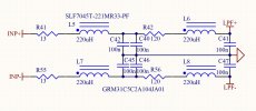
I think in order to left some space for ever try to measure some DUT with just a little bit higher output impedance, wee need a switch for the parallel resistors of voltage divider as well
IMG_0313.jpeg
 

sarieri

Senior Member
Forum Donor
Joined
Mar 1, 2023
Messages
333
Likes
216
Let me know if you guys ever want to put this thing in production. Btw, I did a simulation of putting 34/21.5ohm after 500ohm. Looks like a 2dB roll off at 20khz
 
OP
M

mcdn

Addicted to Fun and Learning
Forum Donor
Joined
Mar 7, 2020
Messages
578
Likes
805
Let me know if you guys ever want to put this thing in production. Btw, I did a simulation of putting 34/21.5ohm after 500ohm. Looks like a 2dB roll off at 20khz
Oh yes, that is ugly. 4.5k before is much better. Your breadboard layout is lovely and simple. I suspect the PCB layout can be improved a lot, especially to include better inductor spacing. @Hipocrates I don't think compactness is a goal, we can use the full 180x90mm of the original PCB, or maybe 170x80mm to help fit more cases?
 

Hipocrates

Member
Joined
Dec 31, 2018
Messages
86
Likes
93
Location
Costa Rica
Oh yes, that is ugly. 4.5k before is much better. Your breadboard layout is lovely and simple. I suspect the PCB layout can be improved a lot, especially to include better inductor spacing. @Hipocrates I don't think compactness is a goal, we can use the full 180x90mm of the original PCB, or maybe 170x80mm to help fit more cases?
Sure thing, and you want more space between the inductors right?
 
OP
M

mcdn

Addicted to Fun and Learning
Forum Donor
Joined
Mar 7, 2020
Messages
578
Likes
805

Hipocrates

Member
Joined
Dec 31, 2018
Messages
86
Likes
93
Location
Costa Rica
Where did you get your Neutrik and Schneider 3D models?
I think it was 3d central or 3dgrab, I attached them as files just in case
 

Attachments

  • Neutrik NC3FAH2.zip
    1 MB · Views: 13
  • Neutrik NC3MAH-0.zip
    533 KB · Views: 16
  • 3D.zip
    65.4 KB · Views: 13
OP
M

mcdn

Addicted to Fun and Learning
Forum Donor
Joined
Mar 7, 2020
Messages
578
Likes
805
OP
M

mcdn

Addicted to Fun and Learning
Forum Donor
Joined
Mar 7, 2020
Messages
578
Likes
805
@Hipocrates I'm having real trouble with putting a sensible divider network in front of the filter. Using higher resistor values than 1k total starts changing the filter response. Using lower values than 1k makes extreme power demands.

The initial assumption was that this feature is going to be used for power amp measurement where the input voltage could be >100Vrms. Using a total resistance of ~1kOhm ((680+220)/100) and input voltage of 140V (to meet the AUX-0025 spec), the power dissipated in the top of the divider network is almost 10W per leg: (140*0.9)^2/900, which is expensive and consumes a lot of space.

We could limit the recommended voltage when using the divider to 60Vrms, which would mean we could use a 2W 680R and 0.5W 220R. That's still 900W into 4 ohms. What do you think?
Or alternatively we drop the feature entirely, and leave the problem of gain reduction to the user?
 

BR52

Addicted to Fun and Learning
Joined
Apr 3, 2021
Messages
573
Likes
494
Location
Germany
@Hipocrates I'm having real trouble with putting a sensible divider network in front of the filter. Using higher resistor values than 1k total starts changing the filter response. Using lower values than 1k makes extreme power demands.

The initial assumption was that this feature is going to be used for power amp measurement where the input voltage could be >100Vrms. Using a total resistance of ~1kOhm ((680+220)/100) and input voltage of 140V (to meet the AUX-0025 spec), the power dissipated in the top of the divider network is almost 10W per leg: (140*0.9)^2/900, which is expensive and consumes a lot of space.

We could limit the recommended voltage when using the divider to 60Vrms, which would mean we could use a 2W 680R and 0.5W 220R. That's still 900W into 4 ohms. What do you think?
You have to take care of the higher currents as well because of the coupling to the filter. A bigger distance would be needed.
 

sarieri

Senior Member
Forum Donor
Joined
Mar 1, 2023
Messages
333
Likes
216
Ivan made this some point last year. It was originally meant to be part of the Cosmos APU but deleted due to people asking for 48V phantom power. It has steeper slope than a 2nd order LPF. Maybe you guys can take a look for reference.
 

Attachments

  • 2022-07-02_11-52-21.jpeg
    2022-07-02_11-52-21.jpeg
    182.2 KB · Views: 23
OP
M

mcdn

Addicted to Fun and Learning
Forum Donor
Joined
Mar 7, 2020
Messages
578
Likes
805
I think I’ll just drop the feature. Anyone seriously testing at high voltages will need to find another way, like a separate divider or tapping their dummy load, or using an active downscaler
 

MCH

Major Contributor
Joined
Apr 10, 2021
Messages
2,655
Likes
2,262
I think I’ll just drop the feature. Anyone seriously testing at high voltages will need to find another way, like a separate divider or tapping their dummy load, or using an active downscaler
I would personally leave the footprints in but unpopulated and with jumpers to bypass so user can choose. Having the possibility to have the voltage divider in the same board is super convenient.
 

Hipocrates

Member
Joined
Dec 31, 2018
Messages
86
Likes
93
Location
Costa Rica
I think I’ll just drop the feature. Anyone seriously testing at high voltages will need to find another way, like a separate divider or tapping their dummy load, or using an active downscaler
Agree
 
OP
M

mcdn

Addicted to Fun and Learning
Forum Donor
Joined
Mar 7, 2020
Messages
578
Likes
805
I've had one more go, this time putting a full divider network post-filter (as opposed to v1, where the divider used the input impedance of the DAC). It works fine, and all resistors are under 10k and 1W or less even with a 140Vrms continuous signal. I don't love it but it does the job, and is easily bypassed with 5mm of hookup wire.

board_3d.png
 
Last edited:

Hipocrates

Member
Joined
Dec 31, 2018
Messages
86
Likes
93
Location
Costa Rica
140Vrms continuous signal.
Holly molly!! What kind of amplifiers you guys test? that signal would be an 5000W @ 4Ω amp o_O

My 15A breaker will trip at 1800W and my most powerfull amp is 300W

For my application I'm looking more for crossover distortion and maybe THD+N @ 1w
 
Last edited:

sarieri

Senior Member
Forum Donor
Joined
Mar 1, 2023
Messages
333
Likes
216
Holly molly!! What kind of amplifiers you guys test? that signal would be an 5000W @ 4Ω amp o_O

My 15A breaker will trip at 1800W and my most powerfull amp is 300W

For my application I'm looking more for crossover distortion and maybe THD+N @ 1w
I thought for Single End AMPs like Hypex offerings, you are basically using only half of the LPF. So actually only 1200W.
 

sarieri

Senior Member
Forum Donor
Joined
Mar 1, 2023
Messages
333
Likes
216
I'm getting the coilcraft inductance. I will update in a few days.
 
Top Bottom