• WANTED: Happy members who like to discuss audio and other topics related to our interest. Desire to learn and share knowledge of science required. There are many reviews of audio hardware and expert members to help answer your questions. Click here to have your audio equipment measured for free!

DIY amp testing (with AES17 filter)

OP
M

mcdn

Addicted to Fun and Learning
Forum Donor
Joined
Mar 7, 2020
Messages
578
Likes
805
-133dB H3 at 5Volt is not complying with Amirm’s measurement. He measured -140dB H3 at 4V output. H3 at 5V should be even lower. The difference of measurements between AP and E1DA may have something to do with AP’s autorange. The kink in Amirm’s SINAD and measured level graph is AP adjusting it’s input sensitivity. I found that once it reaches around 120 THD+N, APU+ADC always gets better measurements than Amirm’s AP.
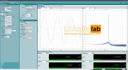
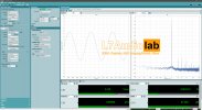
I mean yes, true, but even the actual AP AUX0025 is only specced to -110 dB distortion, so we are still doing a lot better than that!

Ultimately the AUX-0025 isn’t designed for DAC testing down at these levels. It does fine down to -120dB or so, but really it’s for testing power amps.

I am still curious about that extra THD and lower noise with the APU in use in your measurements.
 

sarieri

Senior Member
Forum Donor
Joined
Mar 1, 2023
Messages
333
Likes
216
I am still curious about that extra THD and lower noise with the APU in use in your measurements.
According to Ivan, extras there just means that AP is too noisy. Its autoranger further caused some disparities in lower voltage testings comparing to E1DA setups, where input sensitivity is fixed. Anything beyond 124-125 THD+N is beyond AP’s capability. It will need a notch filter for more accuracy. L7 Audio Lab tested Topping D90SE with APU+APx555B before and the result was around 126-127 range.
 

Attachments

  • IMG_0281.jpeg
    IMG_0281.jpeg
    641.6 KB · Views: 25
  • IMG_0282.jpeg
    IMG_0282.jpeg
    642.1 KB · Views: 26

sarieri

Senior Member
Forum Donor
Joined
Mar 1, 2023
Messages
333
Likes
216
I rethought about my measurements posted before and realized that feeding the signal into LPF and then into ADCiso will mess up with the input/output impedance bridging. So here is a set of measurements where the signal from LPF is fed into scalar(200k input impedance) first and then ADC(6.7v sensitivity). The Scalar is in autoranger mode and targets 6.7v. Ivan's LPF has 0/-10/-15dB attenuation. AUX0025 has no attenuation.
D6s(5V)-Scalar-ADCiso.jpg
D6s(5V)-IVAN(0dB)-Scalar-ADCiso.jpg
D6s(5V)-IVAN(10dB)-Scalar-ADCiso.jpg
D6s(5V)-IVAN(15dB)-Scalar-ADCiso.jpg
D6s(5V)-AUX0025-Scalar-ADCiso.jpg

So it looks like AUX0025 does worsen H3 by about 6dB.
Now let's take a look at the Frequency Response. I measured FR after calibrating the setup and made sure that FR is flat without any LPF. The FR is measured with scalar, so impedance matching is not a problem here.
D6s(5V)-IVAN(0dB)-Scalar-ADCiso FR.jpg
D6s(5V)-IVAN(10dB)-Scalar-ADCiso FR.jpg
D6s(5V)-IVAN(15dB)-Scalar-ADCiso FR.jpg
D6s(5V)-AUX0025-Scalar-ADCiso FR.jpg

A summary here: at 20kHz, Ivan's LPF at 0dB has -0.2dB roll off; at -10dB, it has -0.1dB roll off; and at -15dB, it has -0.4dB roll off. AUX0025 has -0.7dB roll off. -0.7dB is a bit too much here, and I think this is probably due to choice of parts and PCB layout.

Lastly, at highest possible precesion, here is the measurements with APU:
D6s(5V)-APU-Scalar-ADCiso.jpg
D6s(5V)-IVAN(0dB)-APU-Scalar-ADCiso.jpg
D6s(5V)-IVAN(10dB)-APU-Scalar-ADCiso.jpg
D6s(5V)-IVAN(15dB)-APU-Scalar-ADCiso.jpg
D6s(5V)-AUX-APU-Scalar-ADCiso.jpg

Notice that with AUX0025 on a breadboard, I get only -0.25dB roll off at 20kHz, and much better THD+N measured with APU-Scalar-ADCiso. I have little clue what's going on and only suspecting it's probably the PCB layout. Inductances too close to each other?
scalar_aux_test.jpeg

The Zip file is attached here with all original REW measurements.
 

Hipocrates

Member
Joined
Dec 31, 2018
Messages
86
Likes
93
Location
Costa Rica
Hey guys, how about something like this based on @sarieri comments. Would this be acceptable?
For this THT version I had this in mind.

./ Shielded inductors (RFS1317-105KL)
./ Cooper pour on top GND, I stiil need to do some stiching andmaybe calculate a 'guard ring' around the PCB?
./ Vishay CPF resistors.


1708528159281.png


1708528210222.png


1708528337216.png
 

sarieri

Senior Member
Forum Donor
Joined
Mar 1, 2023
Messages
333
Likes
216

Hipocrates

Member
Joined
Dec 31, 2018
Messages
86
Likes
93
Location
Costa Rica
I'm finishing the board however I have a couple questions about the voltage divider (10:1)

I'm removing the 10Ω in series with 800Ω (unusual value) for a 910Ω (common value) with a 100Ω, for a 0.99V.
If precision is a must would you guys like me to install a trimpot in series with a resistor?
Why not go up in resistance for the voltage divider? eg 8.2Kin series with a 2KΩ trimpot to get 9K and 1k, and then get exactly 1V
 
Last edited:

sarieri

Senior Member
Forum Donor
Joined
Mar 1, 2023
Messages
333
Likes
216
I'm finishing the board however I have a couple questions about the voltage divider (10:1)

I'm removing the 10Ω in series with 800Ω (unusual value) for a 910Ω (common value) with a 100Ω, for a 0.99V.
If precision is a must would you guys like me to install a trimpot in series with a resistor?
Why not go up in resistance for the voltage divider? eg 8.2Kin series with a 2KΩ trimpot to get 9K and 1k, and then get exactly 1V
I’m no expert on circuit design, but I will quote what Ivan posted in his discord channel here. This probably explain the idea of low impedance.
I posted on diyaudio.com the google translation of my post in russian DIY forum about that idea:
As Cosmos devices become more widespread, more and more questions arise regarding LPF for measuring class D amps. In addition, measurements of some DACs are also complicated by unfiltered RF content.
As I see, users have already rushed to copy the AP AUX0025 filter, which is not optimal or is simply unsuitable for measuring DR of DACs, due to the high impedance = noise, and it may limit class D as well, at least best of Class D amps. In connection with the above, I want to develop the concept of a simple, affordable, and versatile LPF, suitable for both class D and DACs.
Required:
1) low impedance, for the least noise, and minimal distortion.
2) built-in R/R divider with several stages, approximately from 0 to 15 dB.
3) The 4th order of AUX0025 is generally useless, especially if you need a measurement bandwidth of up to 20 kHz, the 2nd order is enough, i.e. LCR about -30db at 400kHz.
4) LPF, of course, is differential(balanced) and capable of operating at different input impedances from 400 ohm Cosmos ADC to 100k Cosmos Scaler.
If there is a divider, then it is advantageous for us to add an LPF after it, so that only the input resistor operates at max voltage, unlike the AUX0025, where all its parts have to be taken for a high voltage. In order not to wind the air coils, you can take a standard SMD part TDK for 1-2A, with a closed core, which will provide immunity from external EMI and distortion below -130dB, which is quite ok for class D and for measuring DAC's DR. You can have two series inductors, for less distortion, and for switching the LPF frequency, if necessary. It turns out that the input resistor will have to be combined from a few MELF0207, about 1000 ohms at maximum, so, to collect a power of 50V^2/1000ohm=2.5W from them in series, and a gold-plated DIP-Switch on them to configure the divider coefficient. Good one 1206 100V 100n C0G/NP0 will give H3 <-140dB at 1kHz and 5V, so not a problem either, especially since <100nF is required. The output resistor of the divider is switchable, in the case of measuring the DAC's DR, i.e. when a divider should be 0 dB, and for class D 200-400 ohm MELF0207 can be used on the same DIP-Switch to give three positions: 200, 400, Off. The output impedance of DACs may be a hundred ohms, but I hope not more nowadays, the switch mentioned above can be useful here, to short one of the composite inductors and adjust the LPF's cutoff. It is clear that due to the very different impedances, such an LPF with the frequency response of a beautiful Butterworth is impossible, I think we can ignore that and prepare several calibrating files for REW, that's a great simplification of HW LPF.
 
  • Like
Reactions: MCH

Hipocrates

Member
Joined
Dec 31, 2018
Messages
86
Likes
93
Location
Costa Rica
I get what Ivan is saying and mostly applies to his filter. Which is awesome!

The circuit proposed in post #63, is a basic voltage divider aiming to 10:1 ratio, before the filter.
I had the idea that was for attenuate the signal to a 10th of their amplitude. Than can be achieved with a 1K and a 110Ω resistor(common values, less resistors, less noise) So for example 39Vin (amp running at 300w) 3.86Vout, so the filter and the cosmos (or whatever interface) do not get damage.
I don't think a DAC signal amplitude is a problem, is too small, noise is, in this case the voltage divider is inactive.
The AUX0025 seems to be inadequate for DACs (maybe is a limitation of the design) , but useful for amplifiers and that's why I'm making this board taking your pointers(attenuation, and monitoring before the filter) and for potentially EMI noise, I'm using smaller footprint components, short traces, ground pours, stitching vias, ''ring guard" and shielded inductors to see how it goes, this while trying to maintain the fabrication cost low. How much noise would be eliminated (if any) we'll see.
 

sarieri

Senior Member
Forum Donor
Joined
Mar 1, 2023
Messages
333
Likes
216
I get what Ivan is saying and mostly applies to his filter. Which is awesome!

The circuit proposed in post #63, is a basic voltage divider aiming to 10:1 ratio, before the filter.
I had the idea that was for attenuate the signal to a 10th of their amplitude. Than can be achieved with a 1K and a 110Ω resistor(common values, less resistors, less noise) So for example 39Vin (amp running at 300w) 3.86Vout, so the filter and the cosmos (or whatever interface) do not get damage.
I don't think a DAC signal amplitude is a problem, is too small, noise is, in this case the voltage divider is inactive.
The AUX0025 seems to be inadequate for DACs (maybe is a limitation of the design) , but useful for amplifiers and that's why I'm making this board taking your pointers(attenuation, and monitoring before the filter) and for potentially EMI noise, I'm using smaller footprint components, short traces, ground pours, stitching vias, ''ring guard" and shielded inductors to see how it goes, this while trying to maintain the fabrication cost low. How much noise would be eliminated (if any) we'll see.
I think the 10 ohm there is supposed to work like a fuse when the input voltage is too high so that other components do not blow up.
I’m not sure about the choice of resistor values. The values picked will affect roll off around 20khz. 1k resistor will result in around 0.5dB roll off and that’s just in theory; in reality, even more. Also, the voltage divider’s impedance should be fine for the AMP, but not so much for the cosmos ADC if the value is too high unless you feed it to Cosmos scalar and then to ADC.
 
OP
M

mcdn

Addicted to Fun and Learning
Forum Donor
Joined
Mar 7, 2020
Messages
578
Likes
805
@Hipocrates that’s brilliant! If it helps at all, 4 layer PCBs are almost the same cost as 2 layer from JLCPCB
 
OP
M

mcdn

Addicted to Fun and Learning
Forum Donor
Joined
Mar 7, 2020
Messages
578
Likes
805
I'm finishing the board however I have a couple questions about the voltage divider (10:1)

I'm removing the 10Ω in series with 800Ω (unusual value) for a 910Ω (common value) with a 100Ω, for a 0.99V.
If precision is a must would you guys like me to install a trimpot in series with a resistor?
Why not go up in resistance for the voltage divider? eg 8.2Kin series with a 2KΩ trimpot to get 9K and 1k, and then get exactly 1V
Honestly I would go the other way and lower the values to reduce the effect on the input impedance. Would it be simpler to put say a 55.5ohm divider resistor after R1/R2? (34+21.5 in E96)
 
Last edited:

Hipocrates

Member
Joined
Dec 31, 2018
Messages
86
Likes
93
Location
Costa Rica
I think the 10 ohm there is supposed to work like a fuse when the input voltage is too high so that other components do not blow up.
Fusible resistors, oooh very 70s, I get it. I'll finish your board exactly as post #63 just in case. when ready, I'll post here the schematic, gerbers and BOM from mouser, just in case someone wants to play with it. ;)
4 layer PCBs are almost the same cost as 2 layer from JLCPCB
It would be a stack-up of
-GND-
-SIGNAL-
-SIGNAL-
-GND-
Like a coax, that sounds cool.

Would it be simpler to put say a 55.5ohm divider resistor after R1/R2?
I'm still confused about the function of the voltage divider on this application, where I come from is just that... a voltage divider or an attenuator.
But here it seems that it function as a filter, and in this application it seems how precise the output voltage is do not matter, what matters is how affects frequency specially a that very low level of noise. That's new to me and I find it very intriguing.

I'll look for information about it to see if I can follow you guys better. Thank you guys very fun stuff
 
OP
M

mcdn

Addicted to Fun and Learning
Forum Donor
Joined
Mar 7, 2020
Messages
578
Likes
805
I’m no expert on circuit design, but I will quote what Ivan posted in his discord channel here. This probably explain the idea of low impedance.
Ivan is clearly a circuit design master, but I think he's missing the point a bit around this DIY AES17 project. If we relax the voltage requirement (e.g. for DAC measurement) then it's much easier to find components. And if we relax the requirement to meet the AES17 standard, then the circuit becomes a lot simpler too. But then it wouldn't be a DIY AUX-0025!
 
OP
M

mcdn

Addicted to Fun and Learning
Forum Donor
Joined
Mar 7, 2020
Messages
578
Likes
805
Fusible resistors, oooh very 70s, I get it. I'll finish your board exactly as post #63 just in case. when ready, I'll post here the schematic, gerbers and BOM from mouser, just in case someone wants to play with it. ;)

It would be a stack-up of
-GND-
-SIGNAL-
-SIGNAL-
-GND-
Like a coax, that sounds cool.


I'm still confused about the function of the voltage divider on this application, where I come from is just that... a voltage divider or an attenuator.
But here it seems that it function as a filter, and in this application it seems how precise the output voltage is do not matter, what matters is how affects frequency specially a that very low level of noise. That's new to me and I find it very intriguing.

I'll look for information about it to see if I can follow you guys better. Thank you guys very fun stuff
The purpose of the divider is to allow the use of an ADC with e.g. 10V input range to test an amplifier with e.g. 50V output. A 20dB attenuator does this nicely, but if it goes before the filter input resistors I worry it will affect the response and increase the input impedance too much, since it would have to use quite high value resistors.

I'm thinking something like this, after R1/R2 would be better:
Screenshot 2024-02-23 at 10.25.32 am.png
 
OP
M

mcdn

Addicted to Fun and Learning
Forum Donor
Joined
Mar 7, 2020
Messages
578
Likes
805
It would be a stack-up of
-GND-
-SIGNAL-
-SIGNAL-
-GND-
Like a coax, that sounds cool.
I am only an amateur, but I don't think it's usually recommended to have ground pours on both the top and the bottom of a board?
 

Hipocrates

Member
Joined
Dec 31, 2018
Messages
86
Likes
93
Location
Costa Rica
I am only an amateur, but I don't think it's usually recommended to have ground pours on both the top and the bottom of a board?
Some are against, some other says is better and make the case that even help to the board not to bend... I'm just an enthusiast that make ground stars on my amps. This whole filter thing is very new to me. You are the leading voice here my friend, if you think is not a good thing, off with the ground pour on the top!

I forgot to add, that one of the reasons that I post what I'm doing is to see if I'm screwing up something.

Regarding the stack up I said.

 
Last edited:
OP
M

mcdn

Addicted to Fun and Learning
Forum Donor
Joined
Mar 7, 2020
Messages
578
Likes
805
Notice that with AUX0025 on a breadboard, I get only -0.25dB roll off at 20kHz, and much better THD+N measured with APU-Scalar-ADCiso. I have little clue what's going on and only suspecting it's probably the PCB layout. Inductances too close to each other?
@sarieri can you post a photo of your breadboard setup? And thank you for the extra testing!
 
OP
M

mcdn

Addicted to Fun and Learning
Forum Donor
Joined
Mar 7, 2020
Messages
578
Likes
805
So it looks like AUX0025 does worsen H3 by about 6dB.
Yes, but remember it was never meant to measure DACs! It's still giving -123dB of THD+N in your final measurement. Hopefully with your input and the work by @Hipocrates we can improve it further :)
 
Top Bottom