• WANTED: Happy members who like to discuss audio and other topics related to our interest. Desire to learn and share knowledge of science required. There are many reviews of audio hardware and expert members to help answer your questions. Click here to have your audio equipment measured for free!

DIY amp testing (with AES17 filter)

mcdn

Addicted to Fun and Learning
Forum Donor
Joined
Mar 7, 2020
Messages
625
Likes
850
Update May 2024:

Version 2 of the board is now the default at https://github.com/mattclarkdotnet/aes17_filter_25/

v1 had good performance that equalled the AP SYS-AUX-0025. With the help and feedback of @sarieri @Hipocrates and others V2 improved high power handling, tightened tolerances, made the PCB more compact, and reduced the 3rd harmonic distortion below -136dB. Other changes are listed in the readme file on GitHub. I've built and tested one to make the new measurements, but it didn't include the output attenuation option. If you don't want attenuation just leave out R11-R16 and jumper the connection.

Screenshot 2024-02-28 at 10.03.10 am.png


Original post:

I'm a software guy by profession, so looking for help from the hardware peeps! The backstory is that I promised here a few months ago to test a 4 channel TPA3255 module when I received it, and realised I need a decent filter for class D testing. And a voltage divider. And over voltage protection for my ADC. And load switching. And other stuff probably.

Now I can't afford an Audio Precision filter, let alone an analyser, so I thought I'd spec out something that could be ordered as an assembled PCB from JLCPCB.

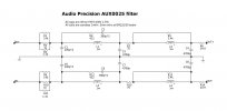
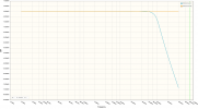
The AP AUX-0025 specs as read off the graph on the AP website are approximately:
* -20dB @ 150kHz
* -40dB @ 200kHz
* -60dB @ 250kHz
* 20-40kHz deviation < 0.1dB

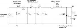
We can get pretty close with a 5th order Legendre filter, with variation below 35kHz < 0.1dB for a 100kOhm load. At ADC input impedances around 10kOhms this widens to ~0.3dB.

After some mucking around with CircuitLab I got this: (all series resistances are modelled in the params for the inductors and caps)
aes17-filter-2.pngsimulation.png
Does this have a hope in hell of working?
 
Last edited:
Terrific info @staticV3 ! The AUX0025 is rated to 170V, is high precision, comes with a warranty, and so on.

It's also a balanced design - is that needed for power amp testing?
 
and it's also really easy to DIY ;)
Yes, but it does take some sourcing skills for tricky components, PCB design, soldering, and a lot of other sweat. I was thinking if maybe we could create an easy to order option that would enable more people to do testing themselves.

The AUX0025 now I look at it has an XLR input wired as you would expect from the schematic. But also some banana sockets where + and - are wired to pins 2 and 3, with no ground connection to pin 1.

A power amp has a differential output to the speakers from the speakers point of view. The speaker itself isn't grounded. So whether the amp itself runs off a balanced or single ended power supply (with respect to safety ground), is not important? Or do I have that wrong?


AUX-0025.jpg
 
A power amp has a differential output to the speakers from the speakers point of view. The speaker itself isn't grounded. So whether the amp itself runs off a balanced or single ended power supply (with respect to safety ground), is not important? Or do I have that wrong?
With single-ended/differential, I was referring to the output stage, not the power supply.

A differential Amp (also called BTL) requires a differential filter, like the AUX0025.
 
With single-ended/differential, I was referring to the output stage, not the power supply.

A differential Amp (also called BTL) requires a differential filter, like the AUX0025.
I know the difference between a BTL and SE amp, but I don’t understand why, to take an example, a TPA3255 amp in SE mode would need a different filter configuration attached to it than the same amp in BTL mode. From the point of view of the load and the filter it’s all just ’differential signal’ unless there’s significant DC offset. Since very smart hardware people build filters with balanced topologies I must be missing some key point!
 
Since very smart hardware people build filters with balanced topologies I must be missing some key point!
Indeed - and that's the input following the filter. It is generally balanced with a ground potential shared with the rest of the system.

It may be easier to understand the problem by assuming for a moment that we're not dealing with a filter but rather a resistive attenuator to mic level, say 100:1 or something.
btl-seatten-cmissue.png

As simulation shows, it basically attenuates fine - see green trace (amplifier output) vs. blue trace (attenuator output).
However, looking at V(out1) vs. ground (red trace) reveals a massive common mode voltage problem at the attenuator output. Your input may not like that very much at all.

Why is this? Well, you may have noticed that attenuator output node out2 is identical to the lower amplifier output node - they are directly connected, come rain, shine or snow. Oops. :oops:

By contrast, a balanced version is suitable for both BTL and SE outputs. SE operation basically eliminates the lower half, as that input is connected to ground elsewhere. Plus, if you just hook out amp_out+ to filter_in+ and amp_out_gnd to filter_in-, you're also basically avoiding a ground loop.
 
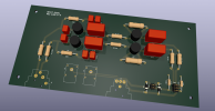
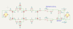
@AnalogSteph , @staticV3, here's a design I knocked up in KiCad. Somewhat simplified compared with the AP one, mainly by using more standard values - it sims out much the same though. I also added test sockets for a multimeter, switchable protection diodes, and a switchable voltage divider.

Before I order the PCB etc, can anyone see anything that needs fixing? Once it's all working I'll publish the KiCad files in case anyone else wants to make one.

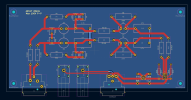
Screenshot 2023-08-06 at 10.50.37 am.pngScreenshot 2023-08-06 at 10.49.38 am.pngScreenshot 2023-08-06 at 10.49.14 am.png
 
@AnalogSteph , @staticV3, here's a design I knocked up in KiCad. Somewhat simplified compared with the AP one, mainly by using more standard values - it sims out much the same though. I also added test sockets for a multimeter, switchable protection diodes, and a switchable voltage divider.

Before I order the PCB etc, can anyone see anything that needs fixing? Once it's all working I'll publish the KiCad files in case anyone else wants to make one.

View attachment 303837View attachment 303838View attachment 303839
Forgot to mention:
  • XLR pin 1 is connected at both ends to a ground pour covering the entire back side of the PCB
  • The XLR chassis ground connections are not routed to the PCB, so the whole chassis is ungrounded. This made sense to me as it is a purely passive device
  • The "virtual ground" between the filter caps is not physically connected to the ground plane/pin 1.
  • I did my best to keep the low-impedance paths for the + and - signals as physically close together as possible.
  • Simulation plot from KiCad below. It's not taking into account the DCR of the inductors, nor the ESR of the caps. A circuitlab sim I did with both in place was flatter in the audio band.
Screenshot 2023-08-06 at 11.09.02 am.png
 
Last edited:
@mcdn
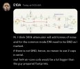
I asked IVX to take a look at your design, as I lack the knowledge to comment.
Here's what he said:
Screenshot_20230806-135724.jpg
 
Wow, I did not expect to get feedback from @IVX ! Thank you!

Interesting about the ground tying between the filter caps, but I am not sure I understand the point correctly. He says on the one hand that there is no need to use paired caps, in which case no connection to ground would be possible. But on the other hand he says that a physical connection to signal ground is needed when using paired caps. I can try with and without and see if there’s a difference. PCBs are cheap.

The inductors are these: https://au.element14.com/wurth-elektronik/7447480102/inductor-1000uh-5-10-5x10-5mm/dp/2211736

As for the divider resistors, they are optional. Audio Precision levels of perfection are not the target! But I do want to measure at levels greater than 8V P-P, so some attenuation is needed somewhere.
 
Luckily my PCB order wasn't started so I updated the design to tie those mid points to ground. My "workshop" is being renovated so it'll be a few weeks before I can build and test the thing.
 
Without grounding these caps the filter has no sense at all, for common mode disturbances at least.
Yep, fixed. Thanks again!
 
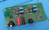
The board is built! I can't test it for a few weeks as I don't have a signal generator that can go >100KHz, so I need to actually hook it up to a class D amp and measure the output spectrum, and to do that I need some stuff that's in storage. I've attached a high res image so anyone who wants to can comment on my soldering :)


tempImagerd0X7r.png
 
I've attached a high res image so anyone who wants to can comment on my soldering :)
ASR scales images down to 1500px wide, so unfortunately that resolution was lost at upload.
 

It's not much higher resolution but enjoy!
 
Back
Top Bottom