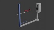
If only, the microphone needs to rotate around the speaker. The same turntable style mechanism can be used to rotate the mic it's just more awkward to realise in practice. Getting the up and down motion combined with the dual scan positions is not so straightforward either.You basically need a turntable for the speaker and a microphone arm that goes up and down, right?
It is all very possible, but just difficult enough to be a pain. Hence years have gone by without a working DIY contraption appearing....
")