• WANTED: Happy members who like to discuss audio and other topics related to our interest. Desire to learn and share knowledge of science required. There are many reviews of audio hardware and expert members to help answer your questions. Click here to have your audio equipment measured for free!

Crown Class-I/BCA topology

Jonas_h

Member
Joined
Mar 27, 2019
Messages
39
Likes
19
I have not seen many topics about this type of topology used in the Crown iTech/MacroTech (The amps marketed for the M2s) and the same topology used in the Mark Levinson No53.

Could be interesting to start a discussion from both a theoretical point of view and also experiences with these amplifiers. Some reading: https://aetechron.com/Service/bca whitepaper.pdf

I have experience from a JBL M2 setup where I went from Crown CTs1200 amplifiers to Crown MacroTech 5000i amplifiers but no scientific comparison was done and there were many changed variables when I did the switch.

Anyone in here with experience and/or opinions? If I lived in the US I would gladly send an amp to the test bench!
 

charleski

Major Contributor
Joined
Dec 15, 2019
Messages
1,098
Likes
2,239
Location
Manchester UK
The whitepaper is from 1998, which explains why some of its concepts are a bit dated. 'BCA / Class-I' looks like simply a proprietary term for Class-D. Most early Class-D amps around the turn of the century weren't that good, which may be why they thought they needed to come up with a different marketing term. Obviously, times have changed.
 
OP
J

Jonas_h

Member
Joined
Mar 27, 2019
Messages
39
Likes
19
The whitepaper is from 1998, which explains why some of its concepts are a bit dated. 'BCA / Class-I' looks like simply a proprietary term for Class-D. Most early Class-D amps around the turn of the century weren't that good, which may be why they thought they needed to come up with a different marketing term. Obviously, times have changed.
I think they are on the 7th-generation Class-I, so they definately kept the concept in their line of new amplifiers. Crown have both Class D and Class-I.

A newer paper here: https://sound-au.com/articles/137234.pdf

As I understand it, it differs from traditional Class D by having double the set of switching output devices working in a push-pull configuration. Each set can run at a lower switching frequency (with less timing issues and more efficiency) but end-result is still a high switching frequency.

Same technology as in the ML No53.

@amirm do you happen to know why ML discontinued it? Outdated technology? Too expensive to produce? Something else? And have you ever had a Class-I amplifier on the test bench?
 

charleski

Major Contributor
Joined
Dec 15, 2019
Messages
1,098
Likes
2,239
Location
Manchester UK
As I understand it, it differs from traditional Class D by having double the set of switching output devices working in a push-pull configuration.
A pair of MOSFETs running in push-pull configuration pretty much defines the switching stage of 'traditional' class-D. See Fig 3 for a couple of push-pull sets in parallel. I really don't see anything in that whitepaper to indicate they're doing anything significantly different.
 

EniGmA1987

New Member
Joined
Dec 31, 2021
Messages
1
Likes
2
I just came across this when searching for some Crown amp stuff. Thankfully not too old of a thread.

A pair of MOSFETs running in push-pull configuration pretty much defines the switching stage of 'traditional' class-D. See Fig 3 for a couple of push-pull sets in parallel. I really don't see anything in that whitepaper to indicate they're doing anything significantly different.
True, but from reading the paper on Class-I, it seems that the Crown design does away with the "time alternation" part of Class-D amps (switching which mosfet of the pair creating the output signal is active) and uses two sets of push-pull mosfets in the same place a Class-D would use one set. It outputs both pairs of waveforms in parallel and interleaves them on together (the interleave signal part is why it is called Class-I). In doing this, the signals both cancel each other out and you get no output. By using two waveforms like this the amp design gets bypasses the need for extremely tight switching timing of a Class-D amp and the time alternation between positive and negative side signal switching, since both positive and negative of each pair are active at once in the Class-I. Now since the waveforms cancel each other out and you have no output, what Crown does to get a signal output is they vary the duty cycle of the pairs of mosfets. To make the resulting waveform go positive, they increase the duty cycle of the first pair and lower the duty cycle of the other by the same amount. Crown also varies the width of the PWM in a way to maintain the same "pulse center" point of the signal of both pairs of mosfets to keep the signal in sync. The way the arrangement works also gives an effective doubling of the switching speed, while keeping switching losses lower than Class-D if they were actually having to run that higher switching speed. Reading about it, the tech seems quite ingenious IMO.
 

charleski

Major Contributor
Joined
Dec 15, 2019
Messages
1,098
Likes
2,239
Location
Manchester UK
uses two sets of push-pull mosfets in the same place a Class-D would use one set.
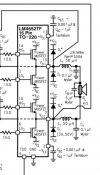
Here’s a schematic for a basic class-D amplifier chip:
34526034-89C6-4E22-8EF6-9D627A93F0EE.jpeg
Two sets of push-pull MOSFETs. Nothing special.
 

DonH56

Master Contributor
Technical Expert
Forum Donor
Joined
Mar 15, 2016
Messages
7,835
Likes
16,498
Location
Monument, CO
AFAIK, which ain't much, class I is not an "official" amplifier class (ends at H). My foggy memory is that Crown implemented it by interleaving the two outputs and that was their "secret sauce". So where a standard class D amp runs the two halves with roughly the same signal (in opposite polarity), Crown's class "I" version changes up the control circuit so the PWM signals are interleaved and not just out of phase. That allowed them to halve the switching frequency. The claim (again, old foggy memory) was that the reduced switching rate of each half would reduce losses and improve efficiency (depends upon the devices and implementation but a reasonable claim).

There have been designs (RF, don't know if in the audio world) that used multi-phased circuits to interleave by a factor of from 4 to 16 (IME, but I do not claim class D amplifier design expertise, so my experience is limited). It did get the switching rate down, but for those designs I did it to make it practical to implement given the limitations of the devices available and desired output bandwidth. IOW, I had to do it to get the bandwidth I needed because devices that switched fast enough to do it in one "phase" were not available. Efficiency was a consideration, and it was a long time ago, but I do not recall it improving efficiency, I think it was actually lower overall due to all the extra circuitry and such. But for audio, comparing a conventional to interleaved x2 design, it might indeed improve efficiency.

The output filter may get complicated with the lower switching rate. Ideal interleaving looks great on paper, but in practice it is hard to exactly align all the edges so you end up with "bleeding" of the lower-rate clock into the output and that must be filtered (depending upon the application it may not be a significant concern).

FWIWFM - Don
 
Last edited:

charleski

Major Contributor
Joined
Dec 15, 2019
Messages
1,098
Likes
2,239
Location
Manchester UK
AFAIK, which ain't much, class I is not an "official" amplifier class (ends at H). My foggy memory is that Crown implemented it by interleaving the two outputs and that was their "secret sauce". So where a standard class D amp runs the two halves with roughly the same signal (in opposite polarity), Crown's class "I" version changes up the control circuit so the PWM signals are interleaved and not just out of phase. That allowed them to halve the switching frequency. The claim (again, old foggy memory) was that the reduced switching rate of each half would reduce losses and improve efficiency (depends upon the devices and implementation but a reasonable claim).

There have been designs (RF, don't know if in the audio world) that used multi-phased circuits to interleave by a factor of from 4 to 16 (IME, but I do not claim class D amplifier design expertise, so my experience is limited). It did get the switching rate down, but for those designs I did it to make it practical to implement given the limitations of the devices available and desired output bandwidth. IOW, I had to do it to get the bandwidth I needed because devices that switched fast enough to do it in one "phase" were not available. Efficiency was a consideration, and it was a long time ago, but I do not recall it improving efficiency (I think it was actually lower overall) due to all the extra circuitry and such. But for audio, comparing a conventional to interleaved x2 design, it might indeed improve efficiency.

The output filter may get complicated with the lower switching rate. Ideal interleaving looks great on paper, but in practice it is hard to exactly align all the edges so you end up with "bleeding" of the lower-rate clock into the output and that must be filtered (depending upon the application it may not be a significant concern).

FWIWFM - Don
That's interesting, thanks. I had a look around and found this paper from 2006, which seems to cover something similar, and there's this patent filed in 2013 by a different group. They all seem to be aimed at getting away with using a lower switching frequency, as you mentioned.
 

ClaudeJ1

Member
Joined
Aug 8, 2021
Messages
34
Likes
29
The whitepaper is from 1998, which explains why some of its concepts are a bit dated. 'BCA / Class-I' looks like simply a proprietary term for Class-D. Most early Class-D amps around the turn of the century weren't that good, which may be why they thought they needed to come up with a different marketing term. Obviously, times have changed.
Lots of square waves in that Paper! Since moving only one electron as the smallest electrical event occurs.........matter is Digital, accumulation of this is Analog.
 
Top Bottom