• WANTED: Happy members who like to discuss audio and other topics related to our interest. Desire to learn and share knowledge of science required. There are many reviews of audio hardware and expert members to help answer your questions. Click here to have your audio equipment measured for free!

Better port design?

KSTR

Major Contributor
Joined
Sep 6, 2018
Messages
2,819
Likes
6,323
Location
Berlin, Germany
All of the above and/or something entirely different?
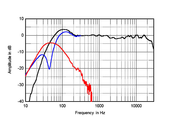
Measuring port output to sufficient precision (lower than -20dB) usually requires that the front output of the mid-woofer must be fully diverted away (isolated acoustic space) from the mic in/at the port, otherwise you mix the true leakage (be it resonant or not) with the bleed from the front output (woofer or midrange) where any amount of addition or cancelling may take place.
For this speaker, the port is quite far away from the woofer so the measured output is cleaner by just that alone (same for rear ports). When the port is directly adjacent to the woofer it is impossible to really see the port's true contribution. Whenever you see a port plot with a notch at some frequency then rising again (as in #27), you can be almost certain this is cancelling and bleed. A way to check this is varying the mic placement, when this results in a different position of the notch/dip the measurement is not covering the real situation.
 
Last edited:

KSTR

Major Contributor
Joined
Sep 6, 2018
Messages
2,819
Likes
6,323
Location
Berlin, Germany
BTW, to check port resonances in isolation during the design phase, one can replace the woofer with a rigid plate and put a small sealed "exiter" mid-woofer inside the cabinet approximately where the cone would be.
And to check the "pan flute" effect (port resonance exited by the midwoofer or midrange front output), now move the exiter mid-woofer near the port on the outside of the cabinet and measure with mic at the inside end of the port.
EDIT: Both effects do actually overlay in practice and this means sometimes (by luck or by design with highly elaborate FEA) they can partly cancel... or add up...
 
Last edited:

mhardy6647

Grand Contributor
Joined
Dec 12, 2019
Messages
11,441
Likes
24,837
The Harbeth Monitor 30.1 is an "evolution" of an early 80's BBC design.

No fancy ports in sight (just a tube with no flange flaring - see below) and yet the roll-off is just about perfect.
Why is that so?
The optimised port location?
The front-facing port?
The larger cabinet size?
All of the above and/or something entirely different?

318harbeth.H302fig3.jpg

https://www.stereophile.com/content...-anniversary-edition-loudspeaker-measurements


8.png


6.png


source
That is refreshingly low-tech looking inside.

1618836590089.png


FWIW (and not that anyone asked), I like the Harbeth ethos -- I can't afford 'em... but I like 'em.
 

kceenav

Member
Joined
Sep 9, 2020
Messages
10
Likes
24
The port in the shown Harbeth box is tuned relatively high, and the box volume is relatively "big" as well (certainly > 25 l, maybe around 30 l?). Thus the port can be kept rather short (which is also helped by its small diameter). So any port resonances will start at quite high frequencies; probably higher than the range stereophile is showing (they show only up to ~800 Hz).
And then it's generally easier to dampen internal reflections/modes at such 'mid' or 'high' frequencies, so that port resonances or leakage won't have a strong impact.

But judging from those pictures Harbeth uses damping material sparsely in this model ...
 

bennybbbx

Addicted to Fun and Learning
Joined
May 27, 2020
Messages
691
Likes
124
Location
germany
I think the problem that there are so much bad port designs out is because the measurement available is not so usefull to show the ugly port noise that can hear on bass and drums. this can done best with a CEA 2010 burst at 50 hz and RTA. see some measure results i do with the CEA 2010 burst at 50 hz on some speakers. the JBL 104 BT is really good

https://www.audiosciencereview.com/...ubwoofer-comparison.20494/page-13#post-842067
 

FeddyLost

Addicted to Fun and Learning
Joined
May 24, 2020
Messages
752
Likes
543
The most radical solution regarding reflex port is to make it vertical and going to some plate (maybe with some damping material attached if we expect mids leakage), like Polk HTS 12, Dali Sub k-14 or Elac Carina (and many other Elac speakers).
All other solutions assume enclosure resonances breaking which usually makes box too expensive for mass market.
 

mononoaware

Addicted to Fun and Learning
Joined
Apr 6, 2021
Messages
816
Likes
669
Unfortunately and ironically, for all Polk talked up its Power Port technology, the L200 had some of the worst port anomalies I've ever seen.

The end result didn't seem to affect the sound too much in my room, but I wasn't exactly looking for it when I listened to the speakers. But it is very evident in the measurements.

The spin overall is solid, but you can see the port anomalies at ~650 and ~1200 Hz:

View attachment 124846

Which are then more evident in the off-axis curves:

View attachment 124847

and then completely obvious in the nearfield measurement:

View attachment 124848

The absolute worst I've measured in this regard was probably the Amphion Argon1, which from my recollection just had a straight hard tube for a port directly behind the woofer:

View attachment 124853The port's midrange peak is nearly as high as its bass peak:

View attachment 124849

It's also worth noting that I believe these port anomalies are actually about 4-6dB higher than they look in nearfield measurements because of baffle loss. Here's the above nearfield measurement when i apply baffle step correction:

View attachment 124852

But then I'm not sure how directivity comes into play for these port issues. Wouldn't the midrange peak be a bit more directional than the bass one, having less influence on the on-axis response with a rear-firing port like this one?

In any case it's evident the port anomalies are having an effect on the on-axis measurement too in the above two cases.

You had me going back to your R200 measurements, as I did not recall the L200’s terrible port resonances in that model.


Interestingly I noticed the 3 main port resonances in the R200 are similar to those present in the L200.

So it seems Polk did something about them in the R200, but when it came to the L200 they treated port resonances with zero effort.
 
Last edited:

ssashton

Member
Joined
Sep 22, 2022
Messages
31
Likes
44
Interesting thread, this.

I've been doing some work on a ported speaker and thought I'd add that what a lot of you are calling midrange-leakage is in fact pipe resonance (which a few people mentioned) however the thing I've been finding is that these resonances cause the port walls to resonate quite significantly, much like a membrane. All of the solutions we find in this thread; KEF's flexible material, Neumans holes covered with damping and the DIY solution with a chamber tapped off the side - they are all doing the same thing which is providing a damped spring to absorb the energy of the pipe resonance pressure peak. Naturally, making the port walls stringer and stiffer only increases the 'Q' of the pipe resonance.

A downside to many of these technologies is that they cause more turbulent air low, so the onset of non-harmonic noises like chuffing will be at a lower level. Not such an issue in larger speakers with space for big ports but in smaller speakers you need to balance the variables carefully.
 

Zinda

Member
Joined
Apr 30, 2022
Messages
19
Likes
3
We have seen recently that many cheap speakers have port resonances. It looks to me they do use basic port (a tube).
I have seen a few better designs, KEF or Yamaha comes to mind. Do you have other examples? I am surprised that
designers are not doing better, this is a very well studied fluid dynamics problem.

Yamaha example (from this website):

View attachment 124787

KEF example (from LS50 meta manual):
View attachment 124788
I did Air Balancing on AC units in big buildings, we used specialized equipment to get readings of air flow through various sized and shaped ductwork. Of course each size and shape move air in a different pattern. We had to take several measurements in round pipe using a peto-tube (Im not sure if the exact spelling it was 35 years ago when I did this)!

We had to divide the pipe into rings or bands that had the same area. So if it was 10" there was a ring lets say 1" on the outer and the next might be 2" wide, the next might be 3" and the center ring would be 4". Now I know these are not correct dimensions for cross sectional equal areas but for this its unimportant. The tube was marked to put it in the center of each ring or band and readings were taken at each point. They showed if the air was moving straight through the pipe or if it was turbulent.

Air normally moves more in the center since the walls have friction that slows it down. The less round any piece of ductwork was, changed friction, which can be calculated by the surface area and opening area (drag coefficient). Since round duct has a surface friction of 1 its the best rating. It uses the least metal to form the largest opening area possible. But since round duct doesnt fit in many applications and it requires a different hanging style square duct is used most often, round duct is used primarily in large commercial buildings that have lots of room and have open ceilings.

The friction is a drag coefficient factor. It affects all air moving through any type of enclosure. We had another tester that could test stuff that wasn't connected to a fan unit. It only works when air is running without any turbulence. To achieve this (since a fan will always have air moving in a turbulent fashion due to the spinning of the blades, even squirrel cage fans do it to some extent) there was a single piece of metal that ran down through the straight part of the supply duct effectively dividing it in 2 parts (larger sizes had a x shaped 4 way divider). That removes the turbulence but it also adds friction to a degree and causes the air to split into 2 areas that have a centered flow. The dividing strip only was in the straight part of the round duct then it changed to whatever size and shape duct or fitting you were testing.

Basically what I'm getting at is if anyone was really serious about air flow through tubes, they could just find all they need to know as tested by IASCA. I learned through a Union Apprenticeship and the results of most tests are published somewhere.

I really dont believe anything that Yamaha has posted since they aren't showing a real test and from what I've seen even smoke tests cannot be plotted without high speed cameras or video to see the exact pattern. It moves so fast it mixes the smoke into a single color and loses its shape.

Smoke tests were only used to show if ventilation hoods were moving fumes away from the person standing in front of the hood. We would adjust the air flow to accommodate that factor. There is a limit on how much air can be sucked into a hood before it causes turbulence in the area around the hood depending on how its shaped and how its positioned. If all 4 sides are open its going to be less effective since air movement can easily pass through the area its trying to vent. The other important factor make up air, it keeps air pressure positive in that area so the vent can capture all the fumes. In a large room with many hoods this can become a huge problem with poisoning workers.

Since there is no fan in ports they wont have as much turbulence But its still important to have the flared portion on the tube to make sure the air has a chance to enter into a shielded area before it passes through the restricted area and the same is true on the outside where air is being pulled back in.

Im not sure what the affect is on air when its being pushed (positive pressure moving to lower pressure under direct mechanical force) opposed to air being sucked do to negative pressure caused by rapid mechanical force. Since the inside will have some turbulence due to shape and distance from obsicles the outside air will not have those obsicles, meaning the tubes flare may not be as important as the inside flare. It all comes down to how the port is positioned in the box. I believe a longer port is always going to be better, as well as the size, to overcome the drag coefficient which will create noise. Theres always the option to use sound deadening insulation inside the port. I know it makes a huge difference in duct work. Even lining the first 2 joints of duct work can remove fan noise, then lining the piece at the diffuser or grill opening will silence any noises of air movement that are caused by restricting duct size as it flows to maintain pressure and move air to each outlet evenly.
 

TurtlePaul

Addicted to Fun and Learning
Joined
May 19, 2020
Messages
632
Likes
1,031
Location
New York
I think one of the more interesting thoughts in port designs are non-circular port cross-sections. For example, ovals, triangles or ports which change aspect over their length. It makes sense that a circular port has the same resonance frequency in 360 degrees as you rotate the port. Similarly a slot loaded port has the slot height and the slot width which usually end up determining the resonant frequencies.

For example, Genelec's ports are not straight round tubes, Kali speakers have a U shaped port, HSU's highest end sub uses triangle ports, iLoud Precision monitors are racetrack shaped.

Of course a circle is easier to cut.
 

Penelinfi

Senior Member
Joined
Apr 22, 2021
Messages
456
Likes
348
I have seen experiments of ports with perforation style holes in the middle of a changing diameter port to reduce resonances. (Maybe hifi compass?)

Also funnily enough I've seen seemingly more decent ports in plastic boombox speakers - larger port, big flares and even slightly changing diameter . At least it seemed like that some years ago; more flares are seen these days it seems
 

Zinda

Member
Joined
Apr 30, 2022
Messages
19
Likes
3
Pitot tube :)

Every aircraft has at least one.

TY! I knew I was probably incorrect since it was told to me by name and I probably only saw it printed a few times. I was an air balance apprentice for 1 year before I went back to sheet metal which I already had 2 years under my belt and there was much more work available. It was nice to see another side of the HVAC trade. Ultimately I ended up in industrial Fabrication that lead to being the shop maintenance mechanic, the shop was a full city block and had numerous buildings each with their own special problems. My list of things fix had no end.
 

Zinda

Member
Joined
Apr 30, 2022
Messages
19
Likes
3
I wonder how much amplifier damping has on ports? First thing I thought when Harbeths entered the discussion was the fact that the amps powering them would most likely be of a higher quality just based on experience of owners.

Once you enter into the Polk range of speakers, there could be a huge variety of amps or receivers or even AV systems. I'm not automatically saying that this is an issue but when you look at damping factors of higher $ amps, you're above 500 and it's not uncommon to see near or over 1000. Plus the fact that the Harbeth will retain an 8Ω load across the spectrum adds to the factor. There's also the wire issue (I will stop right there) well at least we can agree that the gauge of wire has a dramatic affect on damping even at 10'. Just had to mention it while it came to mind and there's no reference in any tests.
 

Zinda

Member
Joined
Apr 30, 2022
Messages
19
Likes
3
My list of things has become quite a chore since last week I had a fire at my home, it melted everything, covered it in black soot and then the firemen came through soaked it all in water, knocked out the ceiling and tore out all insulation then covered it all with another generous supply of water. It's been a week. I've finally accepted it as reality and moved what wasn't destroyed out into a pods storage while they demo the entire inside. I ache everywhere, when you're 60 you have less friends and none of them want to be involved with a chore like this. It should be like a brand new house when they're done. The construction company was supposed to be here today with a dumpster and a crew but nothing so far.
I'm playing retired by refusing to work for anyone have 2 more years before I can call it official!
 

mhardy6647

Grand Contributor
Joined
Dec 12, 2019
Messages
11,441
Likes
24,837
Plus the fact that the Harbeth will retain an 8Ω load across the spectrum adds to the factor.
umm, not really. In fact, this (which is from here, for the "Monitor 30" unsuffixed, dating back to the early 2000s) looks very BBC to me.

1706581850466.png

source: https://www.audiosciencereview.com/forum/index.php?threads/harbeth-monitor-30-speaker-review.11108/

... and the more recent 30.2 from Stereophile:
1706582082107.jpeg

source: https://www.stereophile.com/content...-anniversary-edition-loudspeaker-measurements

These aren't necessarily hard-to-drive loads, but they're not flat, purely resistive loads in their design or behavior, either.

You want an easy-peasy impedance curve? Many Magneplanars offer such. :)
Many have still been tricky loads due to low sensitivity and low impedance, despite behaving like big old resistors.

1706581893314.jpeg

source: https://www.stereophile.com/content/magnepan-lrs-loudspeaker-measurements

here's a Magneplanar with a little more obvious crossover ;)

1706582148630.jpeg

source: https://www.stereophile.com/content/magnepan-magneplanar-mg16qr-loudspeaker-measurements

In the case of the Stereophile plots (EDIT: and the ASR plot above), the solid line is the impedance, and the dashed line is the phase.


Electrostatics, such as the epochal QUAD "ESL-57" act like big old capacitors (which, in essence, they are ;)). Some amplifiers don't like that very much.

1706582436127.gif

nearly a dead short at ca. 20 kHz.
... but boy do they sound grand (within their rather blatant limitations in LF extension and vertical treble dispersion).
source: https://www.audiomisc.co.uk/57and303/interact.html


One takeaway from looking at lots of loudspeaker impedance curves (and their other specs, too): while designers of women's fashion have a reputation for being sadists -- they ain't got nothin' on some of the great loudspeaker designers. :cool:;)
 
Last edited:

mhardy6647

Grand Contributor
Joined
Dec 12, 2019
Messages
11,441
Likes
24,837
My list of things has become quite a chore since last week I had a fire at my home, it melted everything, covered it in black soot and then the firemen came through soaked it all in water, knocked out the ceiling and tore out all insulation then covered it all with another generous supply of water. It's been a week. I've finally accepted it as reality and moved what wasn't destroyed out into a pods storage while they demo the entire inside. I ache everywhere, when you're 60 you have less friends and none of them want to be involved with a chore like this. It should be like a brand new house when they're done. The construction company was supposed to be here today with a dumpster and a crew but nothing so far.
I am so sorry to hear this! Terrible news.
 

dfuller

Major Contributor
Joined
Apr 26, 2020
Messages
3,419
Likes
5,268
I'd say at this point it can be generally established that bass reflex systems hold the least disadvantages in 3 way systems where the midrange is a sealed driver (or is in a sealed sub-enclosure). The leakage and/or pipe resonances above the woofer's crossover point (assuming relatively steep crossover slopes) become effectively non-problems, and in most 3 way designs the woofer crosses well below any typical port concerns. The concern then becomes reducing port noise and keeping ringing and group delay to a minimum.

As for "proper" tuning, that's a matter of opinion. Personally I prefer lower Q (below 0.707) at low Fb as it seems to have the fewest issues.
 
Top Bottom