• WANTED: Happy members who like to discuss audio and other topics related to our interest. Desire to learn and share knowledge of science required. There are many reviews of audio hardware and expert members to help answer your questions. Click here to have your audio equipment measured for free!

best way to measure and evaluate various line driver outputs?

bibio

Member
Joined
Apr 30, 2020
Messages
18
Likes
4
Hello, what is the best way to test and make comparisons between different line level outputs in terms of driving long cables?
From the research I've done the output current is the big deciding factor when in comes to driving long cable runs. What's a practical way of measuring this?
Or is there another industry standard way of making line driver comparisons?
 

DVDdoug

Major Contributor
Joined
May 27, 2021
Messages
3,036
Likes
4,004
How long are your cables? It's usually not an issue if you are going between buildings or something like that. With unbalanced connections within a house, ground loop noise is the most likely problem.

The relationship between voltage, resistance, and current is defined by Ohm's Law. Resistance (and impedance, both Ohms) is "the resistance to current flow".

Cables have a certain capacitance per-foot and higher capacitance makes lower impedance which makes a lower impedance load on the output, "pulling" more current, and potentially dropping the voltage at high frequencies. (Capacitive reactance is a component of impedance).

There is also some resistance per-foot and although it can be an issue with speakers it's not really an issue at line connection impedances. With a very-long run, you might get a fraction of a dB drop. And since the load is normally resistive, any voltage drop caused by resistance is flat across the audio frequency range.

You can calculate the output impedance by adding a load resistor to make a voltage divider and then measuring the voltage drop. The "top resistor" is the built-in effective output impedance (not really a resistor) and the "bottom" resistor is the one you add as a known-load. A 1K resistor load is probably about right but maybe get an assortment of resistors and start with 5-10K.

This can be a bit tricky because you aren't supposed to "match" the impedance. (A matched impedance load would cut the signal voltage in half.) That is, although the output impedance may be less than 1K, it's usually not designed to drive a 1K load and you may not get enough voltage-drop for a good measurement. If the load impedance is too low you can get too much current (more than it's designed for) and stress the electronics, without showing much of a voltage drop.
 

Speedskater

Major Contributor
Joined
Mar 5, 2016
Messages
1,648
Likes
1,370
Location
Cleveland, Ohio USA
With modern solid state equipment, that have a output impedance of about 200 Ohms and an input impedance in the neighborhood of 10,000 Ohms and a reasonable cable construction, output current is not an issue!
Heck, you could use a 1000 foot long RCA interconnect cable to a battery powered input and only lose a dB or 2.
 
OP
B

bibio

Member
Joined
Apr 30, 2020
Messages
18
Likes
4
Hi, this is a for a large installation with really long cable runs 300feet +, and then feeding multiple amplifiers with 10+ parallel connections so the input impedance is well below 10k. Not ideal but nothing can be changed now. Some enthusiastic sales people are claiming that upgrading the unit feeding the amplifiers and driving the long cable runs will make a 'huge' difference. I'd like to find a scientific way of proving/disproving this.
 

RandomEar

Senior Member
Joined
Feb 14, 2022
Messages
335
Likes
776
Hi, this is a for a large installation with really long cable runs 300feet +, and then feeding multiple amplifiers with 10+ parallel connections so the input impedance is well below 10k. Not ideal but nothing can be changed now. Some enthusiastic sales people are claiming that upgrading the unit feeding the amplifiers and driving the long cable runs will make a 'huge' difference. I'd like to find a scientific way of proving/disproving this.
Could you possibly install an active RCA switch or splitter close to the amps? That would get the impedance your source has to drive close to the input impedance of the switch instead of the 10+ parallel connections to your amps. Those would then be driven via much shorter cables from the powered splitter and the cable length between source and splitter would be less problematic.
 

NTK

Major Contributor
Forum Donor
Joined
Aug 11, 2019
Messages
2,719
Likes
6,013
Location
US East
Hi, this is a for a large installation with really long cable runs 300feet +, and then feeding multiple amplifiers with 10+ parallel connections so the input impedance is well below 10k. Not ideal but nothing can be changed now. Some enthusiastic sales people are claiming that upgrading the unit feeding the amplifiers and driving the long cable runs will make a 'huge' difference. I'd like to find a scientific way of proving/disproving this.
A 1000 ft of 24 AWG copper wire has a DC resistance of 28 Ω, and is tiny compared to an input impedance of 10 kΩ. Signal voltage attenuation is not a problem.
Cable_resistance.png
 
OP
B

bibio

Member
Joined
Apr 30, 2020
Messages
18
Likes
4
it would indeed, and that may well happen, (it's not my project) but I'm also just curious how to compare the output drive capabilities of difference pieces of equipment.
 
OP
B

bibio

Member
Joined
Apr 30, 2020
Messages
18
Likes
4
A 1000 ft of 24 AWG copper wire has a DC resistance of 28 Ω, and is tiny compared to an input impedance of 10 kΩ. Signal voltage attenuation is not a problem.
what about overcoming cable capacitance? Would that not cause the HF to start rowing off? Or does that happen regardless of what you are driving the line level signal with?
 

NTK

Major Contributor
Forum Donor
Joined
Aug 11, 2019
Messages
2,719
Likes
6,013
Location
US East
what about overcoming cable capacitance? Would that not cause the HF to start rowing off? Or does that happen regardless of what you are driving the line level signal with?
In that case the line driver will make no difference.
[Edit] You'll need a driver that has low output impedance.
 
Last edited:

Speedskater

Major Contributor
Joined
Mar 5, 2016
Messages
1,648
Likes
1,370
Location
Cleveland, Ohio USA
Hi, this is a for a large installation with really long cable runs 300feet +, and then feeding multiple amplifiers with 10+ parallel connections so the input impedance is well below 10k.
What! You have one XLR 300 foot interconnect cable driving 10 amplifiers?
 

Blumlein 88

Grand Contributor
Forum Donor
Joined
Feb 23, 2016
Messages
20,784
Likes
37,681
Even if those 10 amps pull down the input impedance to 1 k ohm, current is unlikely to be a problem. It would only be 5 milliamps at 5 volts which most gear would handle. What you will need is low output impedance of the device feeding the amps. 100 ohms would probably work, 50 ohms would be better. So measuring that would tell you the main thing.

If you wanted to be sure, I'd grab a headphone amp and use it to buffer the output headed toward the amp.
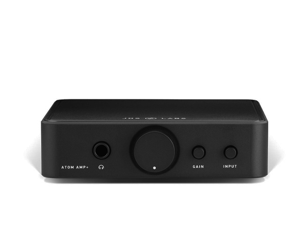
$99 or maybe it went up to $129.


This gives you less than 1 ohm output impedance. Even has a unity gain setting. You might need to use the headphone jack with an adapter to a pair of RCA jacks if that is what you are using. This is fine with headphones with an impedance of only 16 ohms, so it won't care about 1000 ohms you might see with 10 paralleled amps.

Now if you are using XLRs, and with long runs like that I hope you are, then you'll need something else. Nevertheless, if you have something with a 100 ohms or less output impedance you'll be fine.

Also, it might help if you gave us some more details. What are the amps, are they all the same etc etc? What do you have that you plan on using to feed the amps, it may be fine. Specs of that may mean you don't need to do any testing.
 

Blumlein 88

Grand Contributor
Forum Donor
Joined
Feb 23, 2016
Messages
20,784
Likes
37,681
Is this a commercial situation? You can't put the source and the amp closer together than 300ft?
I've seen something like this quite commonly with churches. Put the "sound stack" at the rear and run everything to the front. Would make much more sense to put all of that in an alcove or even room behind the pulpit or stage. Somehow it usually doesn't end up done that way.
 

Blumlein 88

Grand Contributor
Forum Donor
Joined
Feb 23, 2016
Messages
20,784
Likes
37,681
Good engineering practice would be:
Put a buffer at the end of the 300 foot interconnect. A buffer with several outputs.
Yes, this is better. But I've gone into places where they did something like the OP is describing and the wiring was paralleled together in the attic somewhere, and only a couple or 4 wires were into the equipment cabinet.
 

Blumlein 88

Grand Contributor
Forum Donor
Joined
Feb 23, 2016
Messages
20,784
Likes
37,681
Another thought occurred to me for a simple test. Measure at the source end with a short 1 meter cable using a voltmeter and test tones. Measure 400 hz, and 20 khz (don't play this thru speakers as the 20 khz is a danger to tweeters). Then measure again at the far end where the amp inputs are located. See if the 20 khz tone is far lower relative to the 400 hz tone. If so you need some lower output impedance on the source component. If the difference is a db or less don't worry about it.

Now best would be a true RMS voltmeter with response to 20 khz. Even a modest one that rolls off some by 20 khz will work if it responds some at 20 khz. For instance with the short cable you read 2 volts at 400 hz and 1 volt at 20 khz. At the other end you read 2 volts at 400 hz and .5 volt at 20 khz. So you are getting a 6 db drop at 20 khz. Also if using the short cable your 20 khz reading is too low like .1 volt then you need a better meter.

As others are saying, your situation is not optimal in any case, but maybe there are constraints you cannot do much about it.
 

Speedskater

Major Contributor
Joined
Mar 5, 2016
Messages
1,648
Likes
1,370
Location
Cleveland, Ohio USA
Another thought occurred to me for a simple test. Measure at the source end with a short 1 meter cable using a voltmeter and test tones. Measure 400 hz, and 20 khz ............). Then measure again at the far end where the amp inputs are located.
That doesn't compute.
No way that there will be any meaningful difference between the ends of a reasonable speaker cable.
 
OP
B

bibio

Member
Joined
Apr 30, 2020
Messages
18
Likes
4
Is this a commercial situation? You can't put the source and the amp closer together than 300ft?
Yes it's an existing commercial project, I don't personally have any say over this project but it did inspire the question about driving long cables and possible sonic consequences of doing so. And I would like to know would driving the amps line level from different pieces of equipment make a difference.
 

kemmler3D

Major Contributor
Forum Donor
Joined
Aug 25, 2022
Messages
3,358
Likes
6,884
Location
San Francisco
Yes it's an existing commercial project, I don't personally have any say over this project but it did inspire the question about driving long cables and possible sonic consequences of doing so. And I would like to know would driving the amps line level from different pieces of equipment make a difference.
Cable runs of these lengths can cause issues but ~100m is far from unheard-of in the pro audio world. I think the normal thing to do is put the amps and sources in one place, and run 70V to the speakers, wherever those happen to be.

If you need to run XLR to the amps from far away, I think the equipment used does matter but it's not something I've looked into closely. I would suggest asking on a pro audio forum that deals with sound reinforcement more... some folks on this forum do know that space but it's generally more of a home audio / Hifi forum.

That said, in this recent thread by @GXAlan there's a paper that addresses impact on frequency response for cable runs of this length. At 100m you can lose a very noticeable amount of high frequency response, apparently. https://audiosciencereview.com/foru...fference-to-meet-the-audible-threshold.51001/
 

Blumlein 88

Grand Contributor
Forum Donor
Joined
Feb 23, 2016
Messages
20,784
Likes
37,681
That doesn't compute.
No way that there will be any meaningful difference between the ends of a reasonable speaker cable.
Actually computation is at the heart of my post. With 300 feet of cable even 500 ohms of output impedance would cause a significant hf droop of several decibels. 100 ohms or less is likely fine. One important parameter is the cables parallel capacitance. Presuming we don't know the cables my little test would simply tell you if you need different gear to get flat response.

The poster of this came here worried about current which is probably not an issue, but output impedance may be a real issue.

Maybe I misunderstood, but thought this was about line level xlr cables not speaker cables.
 
Top Bottom