Thanks. I don't expect you to do that. Does the Distort software let you view the distortion with fundamental removed, like the Benchmark scope shot shows?Possibly, but it'll take some guessing and a lot of trial and error.

-
WANTED: Happy members who like to discuss audio and other topics related to our interest. Desire to learn and share knowledge of science required. There are many reviews of audio hardware and expert members to help answer your questions. Click here to have your audio equipment measured for free!
You are using an out of date browser. It may not display this or other websites correctly.
You should upgrade or use an alternative browser.
You should upgrade or use an alternative browser.
Benchmark...first watt....ABX...facepalm!
- Thread starter Blumlein 88
- Start date
Thanks. I don't expect you to do that. Does the Distort software let you view the distortion with fundamental removed, like the Benchmark scope shot shows?
Not in the time domain. The current version only shows distortion with fundamental notched in frequency domain.
OK. I think I would like to play around and see if I can figure out how to make that waveform. You say the Distort software can simulate crossover distortion -- can you give me a quick direction on how to do that? I only see how to do harmonic frequencies, but I need to include a component at 1.5X the fundamental frequency, right?
I sent a small donation for being such a PIA.
I sent a small donation for being such a PIA.
Thanks for the donation!OK. I think I would like to play around and see if I can figure out how to make that waveform. You say the Distort software can simulate crossover distortion -- can you give me a quick direction on how to do that? I only see how to do harmonic frequencies, but I need to include a component at 1.5X the fundamental frequency, right?
I sent a small donation for being such a PIA.
The version with crossover distortion is part of a new version of DISTORT that I've not released it yet. Sorry if I gave you the wrong impression. I'll see what I need to do to finish it up. Here's a shot of what it looks like with a fairly large crossover distortion dialed-in:
Bob Cordell plots the inherent output stage distortion at 1:12 of this videoClass AB is always a compromise (when compared to class A) whether you are current dumping and or feedforward, etc. Now, virtually all of these plots show these distortions when driving a resistor, they will look much worse when driving a reactive speaker at such super low levels, thats also a reason the Benchmark is so superb, driving a speaker, at least as far as their white paper abx test, showed their unit sounded better, another Kudo to them and their circuit design.
There are other tests, for example cycling of the drive with high power then low power, on a conventional class AB amp, when you do this, at 0.01 you will see more crossover distortion as the transistor parameters change with heat, and the conventional circuits can not correct for this etc blah blah. However, I should note that even class A needs to stabilize for some time to alleviate this effect (tube or transistor) but once stabilized, no matter if high and low cycling the final output is still near perfect. As the class A is first turned on, the tube or transistor general heating is taking place, and thus even though the bias is solid, the heating of the transistor parameters or the tube elements requires a settling in time.
Class AB Semiconductor amps, no matter what kind , need feedback to stabilize them and drive down distortion from their semiconductor inherent double digits, and Benchmark has created the right kinds to do the job right. Again, real value for money there, and USA made.
His driver board for the ‘220 operates in class A mode up to a bit more than two watts…so I thought this is standard practice for class ab amps…specifically to evade crossover distortion?
tvrgeek
Major Contributor
Going to have to play with DISTORT and see if it can identify the things I hear or do not hear in DACs and amplifiers.
Playing with the Q of filters in APO to see how narrow a slice will reduce the objectional sibilance and brashness without upsetting the overall vocal naturalness. This should be easier with headphones. If not, then it leads me back to amp-speaker interaction. ( New Sennheiser's on order). Through my speakers, 1/2 dB matters quite a bit. I know, it is not supposed to.
Not a clue though why the differences in some DACs with all artifacts below 18 bits could possibly be audible, but in some cases on some music, they are. I want to know why and if it can be fixed or at least identified to avoid.
With all respect to "first watt", where I hear my issue is closer to 10 to 20W. More "enthusiastic" levels. At lower levels, background up to easy listening, I do not notice the issue anywhere as easily. I can, but have to listen for it and that is not as much fun as listening to the music, my actual goal. When really cranked it gets worse until loud enough our sensitivity goes out the window and we can't hear anything anyway. More clues?
When Mr. Pass said the first Watt matters, he meant everything in the first Watt, not at 1W only.
Thanks. Any chance you would include a feature to show just the distortion waveform with fundamental removed? At your convenience, of course; I'm not trying to push too hard.The version with crossover distortion is part of a new version of DISTORT that I've not released it yet.
Thanks. Any chance you would include a feature to show just the distortion waveform with fundamental removed? At your convenience, of course; I'm not trying to push too hard.
Yes, that would certainly make sense, now that you mention it
")
tvrgeek
Major Contributor
Minor tweaks to a DH-220 or 120 can produce 60W, 1K @ .03. I know for a fact as I do. Closer to .003 @ 5W. Don't even need the more complex architecture several have introduced. They may be great. May be way better than mine. Cordell, Self, Diddon, don't remember, showed more class A region is not always better. Careful implementation can approach class B.Bob Cordell plots the inherent output stage distortion at 1:12 of this videofor a class ab Hafler. It’s not as bad as double digits as far as I can see.
His driver board for the ‘220 operates in class A mode up to a bit more than two watts…so I thought this is standard practice for class ab amps…specifically to evade crossover distortion?
Better constant current sources, different balance between input stage local feedback and global feedback changes the balance between even and odd order distortion. Improved power supply and filtering for first and second stage. Biggest change is to two pole Miller compensation. Exicon outputs which are not as good as the Hitachi's, but alas, stability in the real world is not as easy as in Spice and a MOSFET can blow a lot faster than you can hit the power. I know the math says the FET inputs are superior, but I have found them not to be the biggest problem.
Are people forgetting the original Hafler I/O comparison tests?
For fun, I have been modeling a few more changes. Got non-inverting DC servo to behave. That took some changes to the compensation to retain stability. Next is Darlington VAS and maybe a Wilson current mirror in the first stage. I think the mirror change would only be effective if I can get single die matched pairs, thermally linked. Using hand matched now. I might do just as well hand matching and trimming the mirror degeneration. I probably will never do them, as I don't hear any defects now. If I got one of those top few super amps ( purifi I think) and it did sound better, I might be inclined to see how far I could push the MOSFET. It's too good to risk. I can't afford the Benchmark.
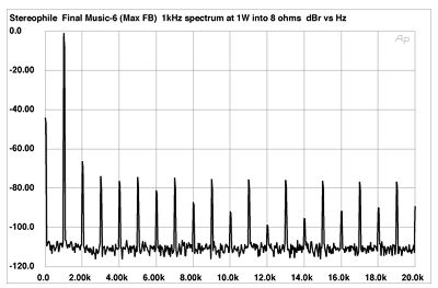
For anyone else interested in trying to create an approximation of the Benchmark scope shot, the measurement of this amp seems to have similar. Figure 18 gives the components.
 www.stereophile.com
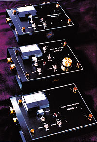
Final Laboratory Music-4 phono preamplifier, Music-5 line preamplifier, & Music-6 power amplifier Measurements part 3
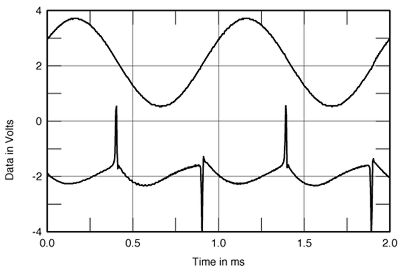
Because the Music-6 is battery-powered, I suspected that it would not have much in the way of output-stage bias current. That this appears to be case is shown by fig.15, which shows the waveform of the distortion riding along with a 1kHz sinewave in the amplifier's output with the feedback at...
www.stereophile.com
For anyone else interested in trying to create an approximation of the Benchmark scope shot, the measurement of this amp seems to have similar. Figure 18 gives the components.
Final Laboratory Music-4 phono preamplifier, Music-5 line preamplifier, & Music-6 power amplifier Measurements part 3
Because the Music-6 is battery-powered, I suspected that it would not have much in the way of output-stage bias current. That this appears to be case is shown by fig.15, which shows the waveform of the distortion riding along with a 1kHz sinewave in the amplifier's output with the feedback at...
Those spikes in the residual are pretty easy to explain. This is an example from Douglas Self for an under-biased class AB amp:
I might not have made myself clear, the double digit distortion is of just the transistor itself, not when it is applied in a circuit with feedback which linearizes it, and what you are pointing out, so just a miscommunication. Operating class AB at class A at super low levels of output power, yes for many somewhere between one and two watts, but for many in the milliwatts they act class A, but still, when you have one device on top of another (class AB) and they both have the same current through them, they still have to balance, and still there is distortion, verses a single sex (SET amp for example), where we are truly pushing the limits of even a AP quality analyzer to find distortion when sitting a class A and amplifying a small signal. HAFLER amps are superb, I have a couple I use as monoblocs, with over 420 watts per channel and they sound and measure very well to this day.Bob Cordell plots the inherent output stage distortion at 1:12 of this videofor a class ab Hafler. It’s not as bad as double digits as far as I can see.
His driver board for the ‘220 operates in class A mode up to a bit more than two watts…so I thought this is standard practice for class ab amps…specifically to evade crossover distortion?
Lets see if I understand the gist of it. Those spikes are created by a high number of odd harmonics all at about the same level, like the spectrum of your crossover distortion simulation shows. Each odd harmonic should be 180 degrees out of phase with the previous odd harmonic. Then the simulated distortion should be aligned with the fundamental so that the spikes occur at the zero crossings of the fundamental. If doing this would be good enough to approximate the distortion Benchmark was testing, then I think I can create this and make files for an ABX. Do you see a problem with my understanding?Those spikes in the residual are pretty easy to explain. This is an example from Douglas Self for an under-biased class AB amp:
View attachment 181053
Lets see if I understand the gist of it. Those spikes are created by a high number of odd harmonics all at about the same level, like the spectrum of your crossover distortion simulation shows. Each odd harmonic should be 180 degrees out of phase with the previous odd harmonic. Then the simulated distortion should be aligned with the fundamental so that the spikes occur at the zero crossings of the fundamental. If doing this would be good enough to approximate the distortion Benchmark was testing, then I think I can create this and make files for an ABX. Do you see a problem with my understanding?
Well, it's the cross-over distortion that generates odd harmonics, not the other way around. My cross-over simulation appears to simulate an "optimally biased" AB amp, as described by Self. I'll need to think about how to simulate an "under-biased" AB amp with those large spikes from Benchmark article.
Here's what the residual looks like in DISTORT (yes, I've added the residual error view):
Here's what Self's measurements show for optimally biased case. Looks similar?
Understood, but I am trying to create the distortion from harmonics so that's how I'm thinking, ha ha. Anyway, this is what I get when doing as I described, jus using Audacity.Well, it's the cross-over distortion that generates odd harmonics, not the other way around.
Understood, but I am trying to create the distortion from harmonics so that's how I'm thinking, ha ha. Anyway, this is what I get when doing as I described, jus using Audacity.
View attachment 181150
Yes, the under-biased cross-over distortion that looks like spikes in the residual generates a mostly non-decreasing (or slowly decreasing) odd harmonics sequence. Cross-over in an optimally biased amp generates odd harmonics with decreasing amplitude. If you add more odd harmonics to your simulation, you'll get sharper spikes in the residual.
Last edited:
Thanks. I will go with doing it this way, then, and add some more harmonics until the spikes look about as sharp as Benchmark's scope shot. Seems to me it should be good enough to be able to do ABX similar to what Benchmark did, if I don't mess up getting the relative levels correct (RMS of the distortion should be 53dB below the RMS of the fundamental if I am understanding their application note correctly).Yes, the under-biased cross-over distortion that looks like spikes generates a mostly non-decreasing (or slowly decreasing) odd harmonics sequence. Cross-over in an optimally biased amp generates odd harmonics with decreasing amplitude. If you add more odd harmonics to your simulation, you'll get sharper spikes in the residual.
restorer-john
Grand Contributor
Thanks. Any chance you would include a feature to show just the distortion waveform with fundamental removed? At your convenience, of course; I'm not trying to push too hard.
Do you want to see an actual amplifier or three with the bias reduced to the point where X/over disortion becomes visible?
(The output of my distortion analyzer after the notch filter buffered and sent to my oscilloscope)
Do you want to see an actual amplifier or three with the bias reduced to the point where X/over disortion becomes visible?
(The output of my distortion analyzer after the notch filter buffered and sent to my oscilloscope)
I do! Always good to validate that simulation can approach reality
I am certainly interested in seeing it, but what I really want to do is create files for ABX. If you are able to record the amp producing 1 KHz sine waves with proper adjustment, and again with crossover distortion, it would be fun to do ABX on those. Especially if you are able to get the relative distortion level similar to Benchmark's test.Do you want to see an actual amplifier or three with the bias reduced to the point where X/over disortion becomes visible?
(The output of my distortion analyzer after the notch filter buffered and sent to my oscilloscope)
Similar threads
- Replies
- 8
- Views
- 859
- Replies
- 91
- Views
- 30K
- Replies
- 319
- Views
- 68K
- Replies
- 30
- Views
- 11K
- Replies
- 136
- Views
- 28K