
This article is to explore how line-level attenuators might affect the signal bandwidth. An attenuator is to reduce the signal amplitude from a source before it is applied to the next component. This could be between a DAC and preamp, or between preamp and power amp. Etc. The reason is usually to optimize the gain range, including noise and distortion as well as range of volume, through the signal chain (see the long thread on signal gain chains here: https://www.audiosciencereview.com/...opagate-through-my-system.33358/#post-1165118). Ideally the attenuators would do nothing but change the signal level, but in the real world they can affect the frequency response as well. And other things, but added noise and distortion from the attenuator itself is usually negligible.
A passive audio attenuator is usually comprised of two resistors, one in series with the source and the other to ground. This divides the signal going to the next component. For this discussion I’ll only consider fixed single-ended (RCA) attenuators; variable and XLR versions work the same way so the general analysis is still valid.
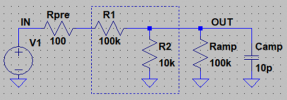
Consider a 20 dB attenuator as shown below. Audio sources are usually low in impedance, perhaps 100 ohms for a SS preamp and 1 k ohms for a tube (with a cathode follower). Audio inputs are usually high-impedance, ranging from perhaps 10k ohms to 100k ohms or more. This means we can neglect cable resistance since it is usually well below 1 ohm for a short interconnect cable (e.g. ~0.2 ohms for 10’). I chose 100k and 10k to provide about 20 dB attenuation; the ideal value is 20*log10[10k/(100k+10k)] = -20.8 dB. With ideal source (0 ohms) and load (infinite ohms, an open) we get 20.8 dB attenuation with no change in bandwidth as expected.


Now let’s make it more interesting by adding source and load impedances plus a length of cable. I’ll use 100 ohms for the source (no capacitance) and 100k ohms plus 10 pF for the load, and assume 6’ of cable with 25 pF/foot of capacitance for 150 pF total (lumped as a single capacitor since cable resistance is negligible) and negligible inductance (at audio frequencies).
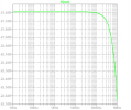
First, a trial without the cable. The attenuator is in the box, with the preamp driving it from the left and amp loading it on the right. The attenuation is changed just a little, to 21.6 dB from 20.8 dB (0.8 dB, about 9% lower than ideal) and the bandwidth is rolled off just a tiny bit (about 0.012 dB at 100 kHz, and only 0.0005 dB at 20 kHz). So far, no impact.


There are two choices for adding the cable. Since the cable’s capacitance is in parallel with the attenuator, usually you put it where the impedance is the lowest, which would be after the preamp (source) since it is only 100 ohms. The result shows almost no change from the previous simulation, with low-frequency attenuation the same, and the amplitude down just 0.012 dB at 100 kHz and 0.0005 dB at 20 kHz as before.


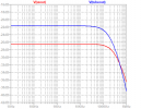
Here is the result if we add the cable after the attenuator, which means after the large series 100k resistor. Now we see the bandwidth is reduced, to -2.31 dB at 100 kHz, though only -0.12 dB at 20 kHz so still almost no impact in the audio band (note that the y-axis scale is different). The roll off at 1 MHz is about 18 dB, which could actually be useful if you are worried about RF noise (interference, RFI). For typical solid-state (SS) sources, it does not appear to be a significant problem no matter where you place the attenuator.


Now repeat, but this time using 1k to approximate a tube preamp’s output. Note my old tube preamp is closer to 300 ohms or so, but I have seen specs as high as 3k, so it depends upon the design. With the attenuator at the preamp’s output, the low-frequency attenuation is now 21.7 dB, a tiny 0.1 dB (1%) difference. Attenuation at 100 kHz is 0.05 dB, again negligible though a hair larger than for the SS preamp. At 20 kHz, attenuation is 0.002 dB, again slightly larger than the SS preamp’s 0.0005 dB but still negligible.


Placing the attenuator at the amplifier’s input has a bigger impact as expected, but still small. The series 100k-ohm attenuator’s impedance swamps the 1k-ohm source output so the result is very similar to that of the 100-ohm SS preamp. Attenuation at 100 kHz is -2.31 dB, and at 20 kHz -0.12 dB, essentially the same as for the SS preamp.


Attenuators do have an impact, and the components and cables used influence that impact, but in the audio band their use should not generally be noticeable except for the reduced signal level. Of course, other combinations of source, attenuator, cable, and load impedances will yield different results, and some combinations might have much greater impact, but those would have to be pretty special cases IME/IMO.
HTH – Don
A passive audio attenuator is usually comprised of two resistors, one in series with the source and the other to ground. This divides the signal going to the next component. For this discussion I’ll only consider fixed single-ended (RCA) attenuators; variable and XLR versions work the same way so the general analysis is still valid.
Consider a 20 dB attenuator as shown below. Audio sources are usually low in impedance, perhaps 100 ohms for a SS preamp and 1 k ohms for a tube (with a cathode follower). Audio inputs are usually high-impedance, ranging from perhaps 10k ohms to 100k ohms or more. This means we can neglect cable resistance since it is usually well below 1 ohm for a short interconnect cable (e.g. ~0.2 ohms for 10’). I chose 100k and 10k to provide about 20 dB attenuation; the ideal value is 20*log10[10k/(100k+10k)] = -20.8 dB. With ideal source (0 ohms) and load (infinite ohms, an open) we get 20.8 dB attenuation with no change in bandwidth as expected.
Now let’s make it more interesting by adding source and load impedances plus a length of cable. I’ll use 100 ohms for the source (no capacitance) and 100k ohms plus 10 pF for the load, and assume 6’ of cable with 25 pF/foot of capacitance for 150 pF total (lumped as a single capacitor since cable resistance is negligible) and negligible inductance (at audio frequencies).
First, a trial without the cable. The attenuator is in the box, with the preamp driving it from the left and amp loading it on the right. The attenuation is changed just a little, to 21.6 dB from 20.8 dB (0.8 dB, about 9% lower than ideal) and the bandwidth is rolled off just a tiny bit (about 0.012 dB at 100 kHz, and only 0.0005 dB at 20 kHz). So far, no impact.
There are two choices for adding the cable. Since the cable’s capacitance is in parallel with the attenuator, usually you put it where the impedance is the lowest, which would be after the preamp (source) since it is only 100 ohms. The result shows almost no change from the previous simulation, with low-frequency attenuation the same, and the amplitude down just 0.012 dB at 100 kHz and 0.0005 dB at 20 kHz as before.
Here is the result if we add the cable after the attenuator, which means after the large series 100k resistor. Now we see the bandwidth is reduced, to -2.31 dB at 100 kHz, though only -0.12 dB at 20 kHz so still almost no impact in the audio band (note that the y-axis scale is different). The roll off at 1 MHz is about 18 dB, which could actually be useful if you are worried about RF noise (interference, RFI). For typical solid-state (SS) sources, it does not appear to be a significant problem no matter where you place the attenuator.
Now repeat, but this time using 1k to approximate a tube preamp’s output. Note my old tube preamp is closer to 300 ohms or so, but I have seen specs as high as 3k, so it depends upon the design. With the attenuator at the preamp’s output, the low-frequency attenuation is now 21.7 dB, a tiny 0.1 dB (1%) difference. Attenuation at 100 kHz is 0.05 dB, again negligible though a hair larger than for the SS preamp. At 20 kHz, attenuation is 0.002 dB, again slightly larger than the SS preamp’s 0.0005 dB but still negligible.
Placing the attenuator at the amplifier’s input has a bigger impact as expected, but still small. The series 100k-ohm attenuator’s impedance swamps the 1k-ohm source output so the result is very similar to that of the 100-ohm SS preamp. Attenuation at 100 kHz is -2.31 dB, and at 20 kHz -0.12 dB, essentially the same as for the SS preamp.
Attenuators do have an impact, and the components and cables used influence that impact, but in the audio band their use should not generally be noticeable except for the reduced signal level. Of course, other combinations of source, attenuator, cable, and load impedances will yield different results, and some combinations might have much greater impact, but those would have to be pretty special cases IME/IMO.
HTH – Don
")