• WANTED: Happy members who like to discuss audio and other topics related to our interest. Desire to learn and share knowledge of science required. There are many reviews of audio hardware and expert members to help answer your questions. Click here to have your audio equipment measured for free!

Aiyima A07 PRO

Holmz

Major Contributor
Joined
Oct 3, 2021
Messages
2,020
Likes
1,242
Location
Australia
It's not about it sounding better with the cover on or off. I can't tell if you are being serious or not.
Serious…
Take the cover, “believes it sound better.”
Listen to it wit eth cover off, and indeed it sounds better…
Don’t look at, and then maybe it sounds the same both ways.

The sound improvements are in regard to the amp being left on for a burn in period. Some swear by this... Others don't get it and then there are outright naysayers. I however have experienced this "Burn In"
Not entirely, it was worded in Socrsatic style.

But you sir... You really should stop taking part of a persons statement out of its context. You took his phrase, butchered it and made it say something different. That is disingenuous and dishonest.

@T&T Said - I have the top cover laying on top, open 1 cm each side so don't get too hot.

@Holmz - You changed this and posted - I have the top cover laying on top, open 1 cm each side, I think sounds better now...

Stop doing this....
BS Sir,
I posted at 10:15 PM my time and his post was edited at 10:53 PM my time.
How was I supposed to quote what he was going modify the post to become, before he actually modified it?

I was not trying to cause offence to @conradj - but I am happy to have him PM me if he has communication style suggestions.

@Scrufboy As it is right now, having “do gooders” coming to the aid could be a bit counter productive… especially when I was posed as an honest question to his post as it was worded… it is a Kafkesque, or along the lines of an Orwellian thought crime.

I’ll accept your apology to the accusation of butchering and dishonesty as a simple mistake, so maybe we move on with less emotion.
You work here is good, and I don’t really want to derail it.


Where were you when i was in college? We'd have had a lot of fun driving the physics lab techs nuts.
^Very good^… I did learn this in a physics lab.
I am just a grasshopper, the professor was the master.
 
OP
Scrufboy

Scrufboy

Active Member
Joined
Dec 8, 2021
Messages
193
Likes
115
Or have the lead feed a buffering cap outside of the unit between the SMPS and the input?

Without an O-scope though, it is hard to tell if it is needed or helping…
I was friends with an Aussie engineer a while back that suggested to me that with the A07 - to make a little box... Put 2 5.5x2.5 DC sockets on it and inside put a 63V 10001uf set of caps. 1 at 10000uf and a other small one at 1uf. I bought them... Never made the box though. He said it is best to put it closer to the amp than the smps. He told me that the way these things work is what gets the amplifiers hot. So this bufferering cap would allow for the amp to draw a steadier supply per se... No fluctuations

Would that be straight wired? Pos leads to and from the Pos on the caps and the same with the neg?
 

Attachments

  • 20230201_231218.jpg
    20230201_231218.jpg
    353.4 KB · Views: 106
OP
Scrufboy

Scrufboy

Active Member
Joined
Dec 8, 2021
Messages
193
Likes
115
I posted at 10:15 PM my time and his post was edited at 10:53 PM my time.
How was I supposed to quote what he was going modify the post to become, before he actually modified it?
I either couldn't know this... Or simply didn't. So for my ignorance, of course - I do apologize. To everyone.

I would have thought that just removing the case cover to make it sound better was preposterous. I'm glad I didn't see it written that way.

One thing that is getting lost is translated sarcasm and humor. I will of course also do my part to mitigate that.
 

Holmz

Major Contributor
Joined
Oct 3, 2021
Messages
2,020
Likes
1,242
Location
Australia
I was friends with an Aussie engineer a while back …
I like ghe bloke bloke already, and I haven’t even me him.


Would that be straight wired? Pos leads to and from the Pos on the caps and the same with the neg?

One might need to worry about inrush current and the SMPS, but probably not.

I was looking at amp the other sday and it said 300,000 uF of capacitance.
That would be 30 of ^those^, but it was a bit bigger of an amp.

I think 1 (or 2) might be dandy.

One could also shove an inductor on the SMPS side.


I either couldn't know this... Or simply didn't. So for my ignorance, of course - I do apologize. To everyone.
No worries… It is an easy thing to miss.
I often look at a post later and correct grammar and tone, or clumsy wording, and I suspect that I am not alone...

I would have thought that just removing the case cover could make it sound better... Was preposterous.

One thing that is getting lost is translated sarcasm and humor. I will of course also do my part to mitigate that.
^metoo^

But my sense of hunour also sometimes doesn’t work well people that prone to being very literal.
 
OP
Scrufboy

Scrufboy

Active Member
Joined
Dec 8, 2021
Messages
193
Likes
115
Update on Bluetooth vs RCA.

To all that responded... Either by purchase choices or with inquiries that asked for verification... You have my apologies.

I just found that the bluetooth device I was using to send data to the A07 Pro amplifier had an EQ boost that reflected the difference in sound between Bluetooth and RCA inputs. I also found a secondary setting that artificially bumps the treble up for your aging ears.

I did a brief sound test just now after noticing this... I shut the EQ down and found it to be much closer to the RCA sound. Then I saw the secondary setting... So tomorrow, I will spend a bit of time with it and address this initial finding and retract any and all previous statements in regards to RCA being dull or Bluetooth being bumped. It was surely bumped, but it was not the Aiyima A07 Pro.

This, in and of itself is good news... But I'm afraid that my lack of attention to detail at the time of posting is unacceptable and embarrassing. I did troubleshoot further... But I should have done this weeks ago or addressed it immediately when the request for verification was made.

Imagine my despair if I had bought that second unit before finding this out... Yikes!
 
Last edited:

Holmz

Major Contributor
Joined
Oct 3, 2021
Messages
2,020
Likes
1,242
Location
Australia
These things happen, and it might be an embarrassment, but integrity is worth a lot In my book.
It is a process of discovery, and you’re doing o’rioght.

As you p’rolly recall.. You could add a note to your original post with an edit. :cool:
 

conradj

Member
Joined
Jan 25, 2023
Messages
63
Likes
37
I was not trying to cause offence to @conradj - but I am happy to have him PM me if he has communication style suggestions.
ok, well this is news to me. i like what Scrufboy's trying to do, i find it very informative; more power to him i say, and i don't think you're trying to offend me, far from it .. just perhaps extra concise with your posts so it's easy to misread them.

You're all fine gents by me. i will play something extra loud with my setup in your honor.
 

conradj

Member
Joined
Jan 25, 2023
Messages
63
Likes
37
I just found that the bluetooth device I was using to send data to the A07 Pro amplifier had an EQ boost that reflected the difference in sound between Bluetooth and RCA inputs. I also found a secondary setting that artificially bumps the treble up for your aging ears.
That's me for sure. i no longer hear any difference when i dial the 16kHz EQ slider way up or down. Ah, Youth; where hast thou flown?
 

conradj

Member
Joined
Jan 25, 2023
Messages
63
Likes
37
--Saw that the OPA1656's i ordered shipped on Feb.1st. Will take 2-3wks to get to me. Meanwhile i freed up some cash and ordered an Aiyima A07 as well, one with LM4562's pre-installed by Aiyima. Get that sometime in March. After that will know better which setup makes what kindo sound.

Will install the A07 at another of my friends' place, where i'd previously put an Aiyima D03, which i'll take back and sell. Or, might try my non-existent surface mount soldering skills on it to change the op amps in that thing.

Next is getting the 48V SMPS, and start looking for capacitors.
 

Zek

Major Contributor
Joined
Feb 17, 2018
Messages
1,611
Likes
2,176
It would be better for ventilation if the holes were on the lower side.

holes.png
 

restorer-john

Grand Contributor
Joined
Mar 1, 2018
Messages
12,716
Likes
38,890
Location
Gold Coast, Queensland, Australia
I was friends with an Aussie engineer a while back that suggested to me that with the A07 - to make a little box... Put 2 5.5x2.5 DC sockets on it and inside put a 63V 10001uf set of caps. 1 at 10000uf and a other small one at 1uf. I bought them... Never made the box though. He said it is best to put it closer to the amp than the smps. He told me that the way these things work is what gets the amplifiers hot. So this bufferering cap would allow for the amp to draw a steadier supply per se... No fluctuations

Would that be straight wired? Pos leads to and from the Pos on the caps and the same with the neg?

The caps would just decrease the supply impedance close to the amp, which may or may not make a small difference to peak power output. The additional supply capacitance may take out the secondary smps' rectifier diodes at switch on, or pop the internal primary fuse rendering the supply dead. Unlikely, but possible, as the caps are essentially a short at switch-on of the SMPS.

Without testing the supply, the amplifier and the losses over the wire from the SMPS to the amp under load, it's just a tweak with dubious benefit and perhaps a downside. If there were significant losses over the wire to the amplifier, you be better off shortening the supply cable to the bare minimum. That's why, in real power amplifiers, the power supply has the lowest possible impedance supply traces/cables and is mounted in the one box, as close to the switching devices as is practical.

Strapping additional PSU caps on little amps like this is really a waste of time. If you are disatisfied with the meagre power output, buy a better amplifier.
 

Holmz

Major Contributor
Joined
Oct 3, 2021
Messages
2,020
Likes
1,242
Location
Australia
The caps would just decrease the supply impedance close to the amp, which may or may not make a small difference to peak power output. The additional supply capacitance may take out the secondary smps' rectifier diodes at switch on, or pop the internal primary fuse rendering the supply dead. Unlikely, but possible, as the caps are essentially a short at switch-on of the SMPS.

Without testing the supply, the amplifier and the losses over the wire from the SMPS to the amp under load, it's just a tweak with dubious benefit and perhaps a downside. If there were significant losses over the wire to the amplifier, you be better off shortening the supply cable to the bare minimum. That's why, in real power amplifiers, the power supply has the lowest possible impedance supply traces/cables and is mounted in the one box, as close to the switching devices as is practical.

Strapping additional PSU caps on little amps like this is really a waste of time. If you are disatisfied with the meagre power output, buy a better amplifier.

While I kinda sorta want to agree…
One would need some measurement of the DC supply voltage and see if it is sagging with a 50/60 (100/120) Hz ripple.

If it was, then more capacitance should lessen the ripple.

Without some objective it is hard to say if it would be needed, in the first place.
And also hard to understand if it helped if one did not remeasure it.
 
OP
Scrufboy

Scrufboy

Active Member
Joined
Dec 8, 2021
Messages
193
Likes
115
That was the original plan. That would indeed be ideal... But you have to see what these chassis halves actually look like in person.

It isn't really doable for me. Not without really precise laser work so you are not ruining the way the pieces fit together or the slot for the PCB. That, or you will be making holes much smaller on the bottom.

We're not done though... I most likely will be rearranging my components and attaching a 92mm silent slim fan to the top of the case... Who knows though... I also want to try a Burson v6 vivid and if I like it, that squashes the fan on top idea. Unless I move it back further on the case. That means more holes! ARGH!

But again... We aren't done here.. So who knows. I was just really wanting to hear the amplifier in the intended chain.

To be fair though... No matter where you put the holes on the sides, it just doesn't matter.

The components heat that air up too fast and it just rises to the top and exits the top vents immediately. The air intake doesn't flow through the case on it's own at a rate that makes the hole placement really matter.

The convection system works though no matter what, as the hot air leaving definitely pulls air in. But not enough to sweep across the inside of the chassis to matter. The 12volt regulators get much hotter than my TPA3255 chip does anyway and those are closer to the side of the case.

Holes on the lower chassis, although they allow air to enter nearer to the PCB, that air heats up a bit quicker and is then forced upwards quicker.

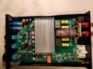
Using a fan changes all of that quite a bit though. And as you can see, I currently have a nice 120mm fan pushing air across and through the amplifier now. This was sufficient for the modified A07, but the Pro unit gets much, much hotter. I'm observing the situation to see what is the next best step.

Remember though - We're not cooling components with this setup. That just isn't possible really...

We are simply allowing the heat to dissipate and leave the case. Nothing we do can change the operating temps of the components in the configuration we choose to run it. We can only help that heat escape.

With what I have done, it may prove to be enough to accomplish that task. It might not.

But - I'm so truly OCD about this that you must know, I want more vents for sure. So we'll see where this goes.

If you do modify the lower chassis, you have to choose what you destroy in order to have holes large enough to draw a reasonable amount of air in. That or we use smaller holes. More holes helps no matter what.

With the same size holes, you either sacrifice or risk the way the two pieces fit together or the slot where the PCB goes. - But, being that there is no PCB being slid into the top half, you can sacrifice that pcb grove in favor of preserving the tongue and groove that marry the two halves together. They are opposing to each other so that makes things quite interesting.

One side of each chassis half has the tongue and the opposite has the grove. The way these are made make the workable space somewhat different for each side. Doable, yes. But with caveats.

You do not have this choice on the bottom. You really only have just under a 1/4" to drill into on the tongue side and even less on the groove side because the groove is actually quite deep.

If you drill to avoid damaging the groove for the PCB, you put that marrying tongue and groove at risk. Smaller holes on the bottom is probably the best bet.

I really don't have the gear to be that precise with the hole size I'm using. But I will most likely vent it further.


The holes I made on the top half completely decimated the unused "pcb" groves on that half. Again, you just have to see how they made this. The sides are also much thicker than the top/bottom

Putting the holes on the bottom half, without extremely precise work, puts you at risk of never being able to slide the board back in if you go too low. Go too high and you may have issues with marrying the pieces together without butchering the chassis further.

In truth..
These vents are only necessary if you are using op-amps that increase the voltages of the signals in the way the SparkosLabs do. I did not experience any heat issues at all with the stock op-amps. Many of you with your IC op-amp choices won't experience increased heat either.

If you do this yourself @Zek please do share your experiences and results.

It would be better for ventilation if the holes were on the lower side.

View attachment 262064
 
OP
Scrufboy

Scrufboy

Active Member
Joined
Dec 8, 2021
Messages
193
Likes
115
The caps would just decrease the supply impedance close to the amp, which may or may not make a small difference to peak power output. The additional supply capacitance may take out the secondary smps' rectifier diodes at switch on, or pop the internal primary fuse rendering the supply dead. Unlikely, but possible, as the caps are essentially a short at switch-on of the SMPS.

Without testing the supply, the amplifier and the losses over the wire from the SMPS to the amp under load, it's just a tweak with dubious benefit and perhaps a downside. If there were significant losses over the wire to the amplifier, you be better off shortening the supply cable to the bare minimum. That's why, in real power amplifiers, the power supply has the lowest possible impedance supply traces/cables and is mounted in the one box, as close to the switching devices as is practical.

Strapping additional PSU caps on little amps like this is really a waste of time. If you are disatisfied with the meagre power output, buy a better amplifier.
The modification that was spoken of was not about the amount of power. It was to mitigate fluctuations that were noticed and possibly responsible for heating up the TPA3255 too much.

I didn't give it too much thought as it was merely a theory the individual had posited.


But thank you for your response.
 
OP
Scrufboy

Scrufboy

Active Member
Joined
Dec 8, 2021
Messages
193
Likes
115
While I kinda sorta want to agree…
One would need some measurement of the DC supply voltage and see if it is sagging with a 50/60 (100/120) Hz ripple.

If it was, then more capacitance should lessen the ripple.

Without some objective it is hard to say if it would be needed, in the first place.
And also hard to understand if it helped if one did not remeasure it.
Yeah... This. Thankfully you have that electro-speak mastered Holmz...
 

restorer-john

Grand Contributor
Joined
Mar 1, 2018
Messages
12,716
Likes
38,890
Location
Gold Coast, Queensland, Australia
While I kinda sorta want to agree…
One would need some measurement of the DC supply voltage and see if it is sagging with a 50/60 (100/120) Hz ripple.

If it was, then more capacitance should lessen the ripple.

Without some objective it is hard to say if it would be needed, in the first place.
And also hard to understand if it helped if one did not remeasure it.

SMPS supplies do not operate at 50/60Hz. They operate from ~50kHz to several hundred kHz.

The input AC is rectified into DC, then switched at high speed into a high frequency transformer.

The SMPS transformer secondaries are rectified by high speed diodes and filtered by low esr capacitors and inductors to provide the DC the amplifier uses. 50/60Hz ripple is not an issue- current delivery and voltage regulation is the issue. Current delivery can be helped by lowering the impedance near the amplifier, but, at the end of the day, if the supply is inadequate it won't help much at all.
 
OP
Scrufboy

Scrufboy

Active Member
Joined
Dec 8, 2021
Messages
193
Likes
115
If I do it to myself I would drill holes in the bottom of the box to allow for easy vertical ventilation.;)
Yeah.. Not possible. The PCB slides into the bottom chassis. It takes up the entire inside of the enclosure. There are no pathways for air to freely flow vertically. You would need holes throughout the PCB to allow for "easy vertical ventilation" Buy one, disassemble it and see for yourself.
 

Attachments

  • 20221212_183056.jpg
    20221212_183056.jpg
    352.6 KB · Views: 120
Last edited:

restorer-john

Grand Contributor
Joined
Mar 1, 2018
Messages
12,716
Likes
38,890
Location
Gold Coast, Queensland, Australia
What I would be looking at is this diode:

1675476243812.png


If D5 is a series polarity protection diode (most likely), you are losing voltage (Po) and that voltage drop (whatever it is) will vary as the current through diode increases. It could also be connected across the supply as polarity protection, but would short in that situation (a less likely implementation)

@pma Do you still have your Aiyma A07? Check out if it has a series diode on the connector and bypass it?
 
Top Bottom