
EXIF68
Active Member
Hello Forum,
a few months ago I decided to build the DXT-MON after studying several German forums and so on. So the problem was to get the wooden parts for the cabinet due to lack of a huge buss saw. After search for a cabinet maker in the web I found the company "Thomaier". This company sells complete sets for the housing in different styles and materials. I decided for plywood with beech veneer. So I ordered the material in the right dimensions, with the options chamfered edges and with service port on the rear side and that all for comparatively less money.
A few days later I get the parcel with the wooden parts and also a parcel with the chassis and the crossover-parts. The advantage was I have only to order the construction plans from zeissmann acoustics and all other parts from the company Thomaier.

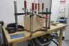
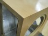
The cabinet side walls gluing together was very easy. They fit perfect together and with "power tape" outside pulling them together was very easy. I only have to check for the Right angles but there were no massive corrections necessary.

Next step was gluing the rear walls into the housing. Due to perfect fit of the 45° chamfers really no problem. No fissures visible on all sides of the cabinet ;-) really fine work.


Next step was damping of the housings with the so called self adhesive "alu butyl". You must wear gloves by handle that thing else you get really horrible black dirt on your hands and you need a lot gasoline to remove that dirt. not fine. In the first step I had only material for one layer. In the construction plans was written to use two layes of alu butyl and additionally one layer of a thin 5mm wallboard. This thins was not included in the kit. And so not used as well.

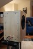
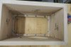
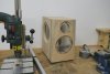
Here the two cabinets without front and before damping. Damping of the rear "service opening" was done.

Internal then nearby all surfaces wer covert by this alu butyl.

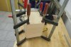
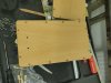
Next step was gluing the really thick front plate to the housings. As you can see, I used really a lot of glue to do this.

And this was the result. The glue comes out of the connections and was running down of the cabinet in and outside. This is not so good because it gets problems for the painting. if this glue is not removed to 100% this will be visible every time!

So here is the situation during drying of the glue and waiting for the next step.

As you can see, the front plates fit together perfect. Not a 1/10 of a mm too big or too small. I would say perfect fit.

Next step was sanding the cabinets and giving them the last "outfit" with a special furniture oil. This oil gives a good lock to the veneer and is really easy to handle. no problems with lacquer noses and such things.
After oiling sanding with 1000-Paper and oiling again... several times. all together 6 layers including polishing. The result was a fine silk-mat surface and really fine to the fingers.

For my opinion: This is parts fitting really good together")
But as mentioned above, I was not carefully enough with removing of the glue. If you look closer you can see a small rest of glue-effect to the oiling process on the adhesive area. But nothing to worry about.
Next step was finishing the cabinets with damping foam and putting the chassis and crossover on the foreseen places.

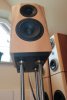
The finished cabinets are looking as good as it gets for this amount of work. Additionally due to lack of enough alu butyl I ordered a 25m roll from a car outfitter. Now There are 3 layers of alu buty inside of the cabinet. This makes the cabinets really heavy and the knock test acknowledges perfect damping with no middle tone rests.

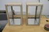
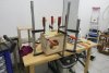
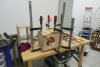
For the stands I was using my older one which I have made 30 years ago for my "first" DIY-Project (The upper plate was made for the measurements of the Dynaudio Gemini). The stands are a little bit too low for this small spears but it works.

Connecting the Speakers to the amp was the last step before listening.

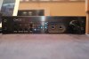
The Amp is this fine part here. Yamaha A-S2100 (2nd hand, low price - less than the half of new price, and really big sound ;-))

My listening room. Some about 20m2. Under the roof of our home. (Right behind you find my other DIY-Speakers: AOS Studio 24XL with Scanspeak 22W8851T00 in 40 liter bass cabinet)

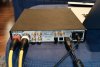
Source of the music is a really old Mac book pro (2011), access to the sound files from a NAS, front end is then a 2nd hand Benchmark DAC2 (I have bought this device with blocked motor pot and also defect power supply. The thin aluminium housing of the device was deformed and so blocked the motor pot. I have corrected this and also oiled the axis of the pot and replaced the build in power supply with an external one form the inter net and made a DC-Port on the backside of the DAC. But this is another story...) and then goes by XLR-Connectors to the Yamaha.
And how does it sound? What should I say? Perfect is understatement ;-) This is a true system for enjoying music (and speec) of all types of music. Bass is really good for the size of the cabinets and middle/heights are perfect. Room impression is fantastic.
Greetings from Austria,
Walter
P.S. apology my bad English. Im not using this language very often ;-)
a few months ago I decided to build the DXT-MON after studying several German forums and so on. So the problem was to get the wooden parts for the cabinet due to lack of a huge buss saw. After search for a cabinet maker in the web I found the company "Thomaier". This company sells complete sets for the housing in different styles and materials. I decided for plywood with beech veneer. So I ordered the material in the right dimensions, with the options chamfered edges and with service port on the rear side and that all for comparatively less money.
A few days later I get the parcel with the wooden parts and also a parcel with the chassis and the crossover-parts. The advantage was I have only to order the construction plans from zeissmann acoustics and all other parts from the company Thomaier.
The cabinet side walls gluing together was very easy. They fit perfect together and with "power tape" outside pulling them together was very easy. I only have to check for the Right angles but there were no massive corrections necessary.
Next step was gluing the rear walls into the housing. Due to perfect fit of the 45° chamfers really no problem. No fissures visible on all sides of the cabinet ;-) really fine work.
Next step was damping of the housings with the so called self adhesive "alu butyl". You must wear gloves by handle that thing else you get really horrible black dirt on your hands and you need a lot gasoline to remove that dirt. not fine. In the first step I had only material for one layer. In the construction plans was written to use two layes of alu butyl and additionally one layer of a thin 5mm wallboard. This thins was not included in the kit. And so not used as well.
Here the two cabinets without front and before damping. Damping of the rear "service opening" was done.
Internal then nearby all surfaces wer covert by this alu butyl.
Next step was gluing the really thick front plate to the housings. As you can see, I used really a lot of glue to do this.
And this was the result. The glue comes out of the connections and was running down of the cabinet in and outside. This is not so good because it gets problems for the painting. if this glue is not removed to 100% this will be visible every time!
So here is the situation during drying of the glue and waiting for the next step.
As you can see, the front plates fit together perfect. Not a 1/10 of a mm too big or too small. I would say perfect fit.
Next step was sanding the cabinets and giving them the last "outfit" with a special furniture oil. This oil gives a good lock to the veneer and is really easy to handle. no problems with lacquer noses and such things.
After oiling sanding with 1000-Paper and oiling again... several times. all together 6 layers including polishing. The result was a fine silk-mat surface and really fine to the fingers.
For my opinion: This is parts fitting really good together
But as mentioned above, I was not carefully enough with removing of the glue. If you look closer you can see a small rest of glue-effect to the oiling process on the adhesive area. But nothing to worry about.
Next step was finishing the cabinets with damping foam and putting the chassis and crossover on the foreseen places.
The finished cabinets are looking as good as it gets for this amount of work. Additionally due to lack of enough alu butyl I ordered a 25m roll from a car outfitter. Now There are 3 layers of alu buty inside of the cabinet. This makes the cabinets really heavy and the knock test acknowledges perfect damping with no middle tone rests.
For the stands I was using my older one which I have made 30 years ago for my "first" DIY-Project (The upper plate was made for the measurements of the Dynaudio Gemini). The stands are a little bit too low for this small spears but it works.
Connecting the Speakers to the amp was the last step before listening.
The Amp is this fine part here. Yamaha A-S2100 (2nd hand, low price - less than the half of new price, and really big sound ;-))
My listening room. Some about 20m2. Under the roof of our home. (Right behind you find my other DIY-Speakers: AOS Studio 24XL with Scanspeak 22W8851T00 in 40 liter bass cabinet)
Source of the music is a really old Mac book pro (2011), access to the sound files from a NAS, front end is then a 2nd hand Benchmark DAC2 (I have bought this device with blocked motor pot and also defect power supply. The thin aluminium housing of the device was deformed and so blocked the motor pot. I have corrected this and also oiled the axis of the pot and replaced the build in power supply with an external one form the inter net and made a DC-Port on the backside of the DAC. But this is another story...) and then goes by XLR-Connectors to the Yamaha.
And how does it sound? What should I say? Perfect is understatement ;-) This is a true system for enjoying music (and speec) of all types of music. Bass is really good for the size of the cabinets and middle/heights are perfect. Room impression is fantastic.
Greetings from Austria,
Walter
P.S. apology my bad English. Im not using this language very often ;-)
Attachments
-
 DSCF9090.jpeg273.8 KB · Views: 381
 -
 DSCF9092.jpeg276.4 KB · Views: 510
 -
 DSCF9094.jpeg287.1 KB · Views: 490
 -
 DSCF9096.jpeg342 KB · Views: 378
 -
 PB250271.jpeg324.5 KB · Views: 338
 -
 PB250272.jpeg333.4 KB · Views: 286
 -
 PB250277.jpeg310 KB · Views: 344
 -
 PB250279.jpeg303.2 KB · Views: 317
 -
 PB250284.jpeg329.1 KB · Views: 314
 -
 PB250285.jpeg332.1 KB · Views: 314
 -
 PB250293.jpeg328 KB · Views: 306
 -
 PC050306.jpeg349.6 KB · Views: 312
 -
 PC050307.jpeg322.7 KB · Views: 355