• WANTED: Happy members who like to discuss audio and other topics related to our interest. Desire to learn and share knowledge of science required. There are many reviews of audio hardware and expert members to help answer your questions. Click here to have your audio equipment measured for free!

FIR filters via REW?

BURNART

Member
Joined
Oct 6, 2021
Messages
9
Likes
1
Hello,
Can anybody help how to make FIR filterset for headphones? I'm familiar with taking measurements and autoeq in REW, but I don't know how to start with FIR fitlers. Is it possible to make it with rephase? Is there any android app to apply them later?
I have Minidsp EARS and Focusrite 2i2.
Best,
Max
 

Tim Link

Addicted to Fun and Learning
Forum Donor
Joined
Apr 10, 2020
Messages
795
Likes
666
Location
Eugene, OR
There's a video by Obsessive Compulsive Audiophile that shows how to use convolution to hit a target. You basically take your measurement, and then set the target curve you want in the EQ section. Save the target curve as a measurement, use the trace arithmetic function to divide the measurement you got by the target curve, inverse that result, and then export the impulse response of the inverted result as a wav. file. Feed that into your convolver and run the result into your headphone amp. It works as expected on my main speakers, with resulting phase very flat and response very close to the target, at the expense of about 30 ms lag.
 
OP
B

BURNART

Member
Joined
Oct 6, 2021
Messages
9
Likes
1
There's a video by Obsessive Compulsive Audiophile that shows how to use convolution to hit a target. You basically take your measurement, and then set the target curve you want in the EQ section. Save the target curve as a measurement, use the trace arithmetic function to divide the measurement you got by the target curve, inverse that result, and then export the impulse response of the inverted result as a wav. file. Feed that into your convolver and run the result into your headphone amp. It works as expected on my main speakers, with resulting phase very flat and response very close to the target, at the expense of about 30 ms lag.
Thanks a lot for link and description!
 

Tim Link

Addicted to Fun and Learning
Forum Donor
Joined
Apr 10, 2020
Messages
795
Likes
666
Location
Eugene, OR
I'll be interested in knowing how it works out for you. One thing that's different than the video is that I don't make a minimum phase version of the inverted files when I'm doing close measurements of the drivers. I think that would apply for headphone measurements too.
 

olieb

Senior Member
Joined
Jul 1, 2023
Messages
371
Likes
607
Feed that into your convolver and run the result into your headphone amp. It works as expected on my main speakers, with resulting phase very flat and response very close to the target, at the expense of about 30 ms lag.
The (stereo) convolution files in the video are about 1.8MB.
Is this typical or can one produce (much) smaller files for use in DSP like minidsp, hypex and so on?
 

Matias

Master Contributor
Forum Donor
Joined
Jan 1, 2019
Messages
5,103
Likes
10,979
Location
São Paulo, Brazil
 

Tim Link

Addicted to Fun and Learning
Forum Donor
Joined
Apr 10, 2020
Messages
795
Likes
666
Location
Eugene, OR
The (stereo) convolution files in the video are about 1.8MB.
Is this typical or can one produce (much) smaller files for use in DSP like minidsp, hypex and so on?
If you open the impulse file in Audacity you'll find that most of it is silent. I clip off the silence in front of and behind the impulse and end up with mono files that are about 6 kB. Stereo would be about double I suppose. I just use the same impulse correction for left and right drivers. Im using 48 KHz sample rate, 24 bit. I don't know why his files are so large. I'd have to watch the video again. Honestly I didn't have luck using the method they way he did, for full room response correction. When I tried it I could always hear weird unintended effects. With the close mic measurements of the drivers and narrow IR windows under 10 cycles I get a good result.
 

ernestcarl

Major Contributor
Joined
Sep 4, 2019
Messages
3,114
Likes
2,335
Location
Canada
The (stereo) convolution files in the video are about 1.8MB.
Is this typical or can one produce (much) smaller files for use in DSP like minidsp, hypex and so on?

Change the sample count during export. You should be able to get away with a smaller value if you decrease the size of the left window:

1710241094208.png 1710241109630.png 1710241120446.png

1710241178695.png 1710241194817.png 1710241470601.png 1710241485075.png

Actually, I have relegated certain minimum phase EQ (e.g. low frequency HPF) instead to my processor's PEQ bank. Why? Well, not including those inside the FIR filter helps to "economize" -- if needed.


Center speaker ~0.7m distance below summed with the sub:
1710242341300.png 1710242348619.png 1710242461710.png 1710242472472.png

LF extension of this speaker is limited and the already steep slope is exacerbated by the room positioning... hence the presence of that dip/gap around the crossover region.
 

olieb

Senior Member
Joined
Jul 1, 2023
Messages
371
Likes
607
Honestly I didn't have luck using the method they way he did, for full room response correction. When I tried it I could always hear weird unintended effects.
Yeah, this method looks all fine on paper, but the measurement is just one single point in space. 5 cm to the side the FR might look different and the filter effect may be all over the place (in MF and HF).
Actually, I have relegated certain minimum phase EQ (e.g. low frequency HPF) instead to my processor's PEQ bank. Why? Well, not including those inside the FIR filter helps to "economize" -- if needed.
Sure, avoiding LF filter will create smaller FIR files. I was just wondering about the ballpark.
 

ernestcarl

Major Contributor
Joined
Sep 4, 2019
Messages
3,114
Likes
2,335
Location
Canada
Sure, avoiding LF filter will create smaller FIR files. I was just wondering about the ballpark.

I think 4k sample count at 48kHz yields a file size of about 16 kb or so — assuming that’s what you are asking.
 

Tim Link

Addicted to Fun and Learning
Forum Donor
Joined
Apr 10, 2020
Messages
795
Likes
666
Location
Eugene, OR
Actually, I have relegated certain minimum phase EQ (e.g. low frequency HPF) instead to my processor's PEQ bank. Why? Well, not including those inside the FIR filter helps to "economize" -- if needed.
I've just been learning the same thing. I'm also applying a 20 ms delayed and inverted signal at about 100Hz because it cleans up the spectrogram nicely at the listening position, getting rid of a 20ms kink in the peak response line. Not sure if it makes a meaningful difference in the sound quality, but it looks nicer.
 

ernestcarl

Major Contributor
Joined
Sep 4, 2019
Messages
3,114
Likes
2,335
Location
Canada
I've just been learning the same thing. I'm also applying a 20 ms delayed and inverted signal at about 100Hz because it cleans up the spectrogram nicely at the listening position, getting rid of a 20ms kink in the peak response line. Not sure if it makes a meaningful difference in the sound quality, but it looks nicer.

Are you describing some kind of active bass absorption/cancelling? Probably needs to be played by different (not the same) speakers or subs at a much lower level and band limited.
 

Tim Link

Addicted to Fun and Learning
Forum Donor
Joined
Apr 10, 2020
Messages
795
Likes
666
Location
Eugene, OR
Are you describing some kind of active bass absorption/cancelling? Probably needs to be played by different (not the same) speakers or subs at a much lower level and band limited.
Yes, that's pretty much what it is. It definitely requires a much lower level and band limiting. It can be played by the same speaker and still work sometimes! The thing is, I've got two woofers in the corner and they may be canceling each other this way. It's always occurred to me that with two speakers in the corners they should be able to at least partially cancel out the front corner bounce from the other speaker. I don't know why it's 20ms that works so well rather than a time that more accurately matches their distance. It could be a combination of their straight line distance plus the distance with 1 bounce off the middle of the back wall into the other corner. That makes me think maybe I should be using two delayed signals, one corresponding to each of those distances.
 

ernestcarl

Major Contributor
Joined
Sep 4, 2019
Messages
3,114
Likes
2,335
Location
Canada
Yes, that's pretty much what it is. It definitely requires a much lower level and band limiting. It can be played by the same speaker and still work sometimes! The thing is, I've got two woofers in the corner and they may be canceling each other this way. It's always occurred to me that with two speakers in the corners they should be able to at least partially cancel out the front corner bounce from the other speaker. I don't know why it's 20ms that works so well rather than a time that more accurately matches their distance. It could be a combination of their straight line distance plus the distance with 1 bounce off the middle of the back wall into the other corner. That makes me think maybe I should be using two delayed signals, one corresponding to each of those distances.

Have you tried simulating beforehand -- rather than adjusting after the fact -- the summed/vector averaged results (e.g. adjusting offset time/delay and EQ of the cancelling IR) in REW? I know this can be performed manually -- but probably difficult to get truly optimal results. Would be nice to have some AI algorithm (e.g. Dirac ART) to perform much of the heavy lifting to be honest.
 

Tim Link

Addicted to Fun and Learning
Forum Donor
Joined
Apr 10, 2020
Messages
795
Likes
666
Location
Eugene, OR
Have you tried simulating beforehand -- rather than adjusting after the fact -- the summed/vector averaged results (e.g. adjusting offset time/delay and EQ of the cancelling IR) in REW? I know this can be performed manually -- but probably difficult to get truly optimal results. Would be nice to have some AI algorithm (e.g. Dirac ART) to perform much of the heavy lifting to be honest.
I have tried some simulating. Rooms never match the simulation it seems. The walls only partially reflect the sound, with some absorption and then later release. That's my guess. Taking pot shots and seeing what happens is the best I've been able to do so far.
 

Tim Link

Addicted to Fun and Learning
Forum Donor
Joined
Apr 10, 2020
Messages
795
Likes
666
Location
Eugene, OR
Today I employed the following method of creating an FIR impulse in REW.

Edit: The following is unnecessarily complex. There's an invert phase option in the trace arithmetic options.

1. Make a target curve.
2. Make that target curve a measurement.
3. Make a minimum phase version of that target curve.
4. Make a flat target curve and make a minum phase version of that. Make it go to zero Hz and make sure the resulting phase is flat.
5. Divide the target curve by the flat target, setting the levels so that no gain can occur so the result has flat frequency response but with inverse phase of the target curve.
6. Multiply the target curve by this inverse phase flat target to get a target curve with flat phase.
7. Divide the measurement by the flat phase target curve.
8. Export the impulse of this for use in your convolver.

This linearizes the phase as much as possible without introducing pre-echo. The measurement never got inverted. Instead the target got inverted, and it has no echoes.

My ears are telling me this is really good! The frequency response is a bit differnent here and there but that can be fixed with a little PEQ and the phase still looks really nice.

I recommend using a measurement that is heavily windowed, like 7 cycles, and add psycho acoustic smoothing as well. The problem with convolution is it doesn't know when to quit. It's too high resolution, which is what can cause all kinds of serious issues.

Linear phase in the crossover zone seems to be very helpful for my unorthodox system that has the high frequency horns horizontall spaced a very significant distance from the woofers. The linear phase time alignment is easier, and seems more positionally robust in terms of avoiding bad cancelations. The problem was that all my linear phase filters were suffering from pre-echo. I think. They were showing some benefits but also degredation. This latest filter method seems like a pure win. It sounds pristine, open, clean.

If anyone has comments about possible issues with this approach or perhaps more straight forward ways to get the same result in REW I'd love to hear from you.

Step Response.jpg


I'm stuck awake and it's almost 1:30 a.m.! Everything I listen to sounds so good! This is by far the best sound I've achieved with my DIY systems. My big horns are sounding sweet in a way that I thought might not be possible.
 
Last edited:

ernestcarl

Major Contributor
Joined
Sep 4, 2019
Messages
3,114
Likes
2,335
Location
Canada
Today I employed the following method of creating an FIR impulse in REW.

1. Make a target curve.
2. Make that target curve a measurement.
3. Make a minimum phase version of that target curve.
4. Make a flat target curve and make a minum phase version of that. Make it go to zero Hz and make sure the resulting phase is flat.
5. Divide the target curve by the flat target, setting the levels so that no gain can occur so the result has flat frequency response but with inverse phase of the target curve.
6. Multiply the target curve by this inverse phase flat target to get a target curve with flat phase.
7. Divide the measurement by the flat phase target curve.
8. Export the impulse of this for use in your convolver.

This linearizes the phase as much as possible without introducing pre-echo. The measurement never got inverted. Instead the target got inverted, and it has no echoes.

My ears are telling me this is really good! The frequency response is a bit differnent here and there but that can be fixed with a little PEQ and the phase still looks really nice.

I recommend using a measurement that is heavily windowed, like 7 cycles, and add psycho acoustic smoothing as well. The problem with convolution is it doesn't know when to quit. It's too high resolution, which is what can cause all kinds of serious issues.

Linear phase in the crossover zone seems to be very helpful for my unorthodox system that has the high frequency horns horizontall spaced a very significant distance from the woofers. The linear phase time alignment is easier, and seems more positionally robust in terms of avoiding bad cancelations. The problem was that all my linear phase filters were suffering from pre-echo. I think. They were showing some benefits but also degredation. This latest filter method seems like a pure win. It sounds pristine, open, clean.

If anyone has comments about possible issues with this approach or perhaps more straight forward ways to get the same result in REW I'd love to hear from you.

View attachment 365213

I'm stuck awake and it's almost 1:30 a.m.! Everything I listen to sounds so good! This is by far the best sound I've achieved with my DIY systems. My big horns are sounding sweet in a way that I thought might not be possible.

Are you correcting the phase here for just the horn? Or a more complex multi-way?

Personally, I don't like to bother with target curves.

I manipulate the excess phase/actual phase manually via rePhase. And then convolve the generated filter(s) with the raw measurement and compare. It's easier to limit/control the adjustments this way and avoid overly aggressive semi-automated results via REW's trace arithmetic.
 

Tim Link

Addicted to Fun and Learning
Forum Donor
Joined
Apr 10, 2020
Messages
795
Likes
666
Location
Eugene, OR
Are you correcting the phase here for just the horn? Or a more complex multi-way?

Personally, I don't like to bother with target curves.

I manipulate the excess phase/actual phase manually via rePhase. And then convolve the generated filter(s) with the raw measurement and compare. It's easier to limit/control the adjustments this way and avoid overly aggressive semi-automated results via REW's trace arithmetic.
It's a two way horn system in this case. I need to understand more about why I'd want to get more on-hands with controlling the phase each step of the way. For now I just use smoothing to make sure my filters are gentle and not overly detailed. I'm surprised at how much is possible with REW. Once I'm more familiar with what needs to be done with greater precision I'll start playing with rephase, knowing then exactly why I need it.

The method I described in that post is overly complex. A function is already included for reversing the phase, making it super easy to remove excess phase, or just flatten the phase if you want.
 
Last edited:

Tim Link

Addicted to Fun and Learning
Forum Donor
Joined
Apr 10, 2020
Messages
795
Likes
666
Location
Eugene, OR
Question: I made an impulse file and it appears to be completely silent. I assumed REW glitched, but when I re-imported that impulse response, there was my measurement in full detail! I checked the impulse in Audacity and I can't see any sound information in there at all. It's flatlined all the way across as far as I can see, which means I have no idea what I can and cannot trim off the "silent" parts.

How does this magic work??

Never mind. I found it. It's just really, really quiet. I amplified the signal a lot and there it is.
 
Last edited:

Tim Link

Addicted to Fun and Learning
Forum Donor
Joined
Apr 10, 2020
Messages
795
Likes
666
Location
Eugene, OR
For those who may be wanting to correct individual drivers and create crossover filters with REW, I've refined a process with better results than ever, using various bits and pieces I've learned from Youtube and here and other forums.

Key point: Minimum phase systems can be modeled quite accurately by REW. That's a great thing because the speaker drivers are minimum phase, and if you apply minimum phase crossovers and EQ to the drivers to get their target response correct, then REW will very accurately match that if you have it generate a "measurement" from the target shape, and then make a minium phase version of that. Measure your EQ'd speaker with crossovers applied and compare it to the artificially generated version made in REW and you'll see very much the same phase response.

So, you can then do a 1/A on the artificially generated measurement from target shape, set the target level higher than the generated measurement, and set allowed gain to zero, and now you have a flat frequency response filter with inverted phase which will allow you to flatten the phase of your driver without actually having to invert the measurement itself. Inverting the measurement is not ideal because the measurement isn't truely anechoic and contains reflections and echoes, little stuff that shouldn't really be included in your correction filter. You can window that out to some degree, and it works pretty good, but then accuracy is compromised.

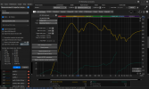
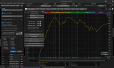
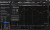
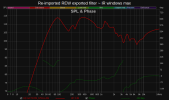
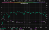
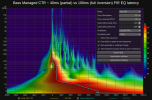
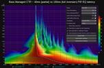
These results were achieved quickly using the method. You can see some sharp notches in the frequency response around 80 Hz due to my bass horns. Those cannot be fixed, so I included them in the target shape by EQing it with a couple notch filters, thus preventing bass in that region from coming in early from the phase correction being over zealous. I could make those a little deeper to get the step response even cleaner. In the spectrogram picture you can see the bass still coming in slightly early at around 88 Hz. I just need to make the notch filters deeper to match the reality so the phase correction doesn't over-do it. The spectrogram tells a lot. I'm super happy to see not a trace of noise coming in before the main pulse.

Impulse.jpg

Spectrogram.jpg

FrequencyandPhase.jpg
 
Top Bottom