• WANTED: Happy members who like to discuss audio and other topics related to our interest. Desire to learn and share knowledge of science required. There are many reviews of audio hardware and expert members to help answer your questions. Click here to have your audio equipment measured for free!

singxer Sa-1 Help, XLR input does not work anymore

Extreme_Boky

Active Member
Joined
Jun 9, 2020
Messages
106
Likes
71
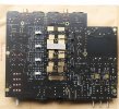
The PCB damage is not that extensive at all; there are 3 tracks that need to be repaired - with a bit of wire... which is really quite simple... even if it warrants buying a brand new soldering iron :)

The tracks are not critical for sound quality because they are not in an audio signal path... I think they are controlling the operation of RL1 and RL2, which in turn do XLR <-> RCA selection.

So really, I'd call it a lesson learned with a repair that will cause no impact on sound quality. We just need to see if the repair will fix the problem...
 

Roland68

Major Contributor
Joined
Jan 31, 2020
Messages
1,460
Likes
1,279
Location
Cologne, Germany
yup, those 4 screw marks are there on the bottom :/ What should I do? I have a guy who does PCB stuff and soldering etc, but I need to tell him exactly what to fix...

I uploaded Hi-res images and a video of the PCB as you requested @Extreme_Boky , you can download the RAR file here... https://drive.google.com/file/d/1ic4cCystT7O9AGsulx33z9vCYdlExH96/view?usp=sharing
Probably lucky in disguise.
These appear to be the traces that lead to the input relays and control the switchover between XLR and RCA inputs.

Before you start soldering/repairing, please carefully scrape the areas next to and between the traces to make sure there is no short between the traces or to ground. Red markings in the picture.
After that, the insulating layer on the conductor tracks in front of and behind the damage must be carefully removed. A fiberglass pencil, fine sandpaper or a sharp, rounded blade are suitable for this. But be very careful, the traces are very thin and delicate.
Then the conductor tracks must be reconnected, 0.2 - 0.5mm wire is sufficient.
Before switching on, make sure that the printed conductors have no contact with each other or with ground.
IMG_3409.JPG
 
OP
T

teruster

Member
Joined
Apr 29, 2023
Messages
12
Likes
4
Meaning, the pcb board was screwed? :eek:
HAHA yeah man, it was screwed for sure but thank god it wasn't screwed beyond repair!

Thank you @Extreme_Boky and @Roland68 ! Yeah it was only one point (which you have mentioned) where the repairs needed to be done on the tracks.
The guy did it in no time and the total cost was less than $2 :) I did extensive testing with all inputs / outputs at all sound levels - everything is good as new!
Note to self : Never mess around with the feet!

P.S. @Extreme_Boky do keep us posted of any mods you wanted to do on this!
 

Attachments

  • IMG_3416.JPG
    IMG_3416.JPG
    90.9 KB · Views: 56
Last edited:

Extreme_Boky

Active Member
Joined
Jun 9, 2020
Messages
106
Likes
71
To do that DC mod properly, those 8 caps and 4 links should be removed entirely from the board, and then copper links should be soldered. This would sound much better than just inserting the little shunts (clips) from the top...

To bypass everything (potentiometer as well) and have XLRs directly coupled straight to the 4 amplifier channels (which would sound superbly impressive), the 4 links should be removed and left open, and then copper wires should be soldered as shown, from the XLR pins to the inputs to those 4 amplifier channels. I'd also cut the PCB tracks (on top side) between 1 and in 1, 2 and in 2, 3 and in 3 and 4 and in 4.
Untitled-1 - mods.jpg
 

Attachments

  • Untitled-1 - mods.jpg
    Untitled-1 - mods.jpg
    373.4 KB · Views: 60
Last edited:
OP
T

teruster

Member
Joined
Apr 29, 2023
Messages
12
Likes
4
damn, iam very tempted to do this! do you think there is any possible downside or risk apart from all the benefits by doing this mod @Extreme_Boky ? the 4 jumpers from the topside should be removed too right?
 
OP
T

teruster

Member
Joined
Apr 29, 2023
Messages
12
Likes
4
you did mention earlier something about feeding it with 2 linear power supplies, would I need to get those or run it as it is?
 

Extreme_Boky

Active Member
Joined
Jun 9, 2020
Messages
106
Likes
71
The external linear power supplies would need to be of good quality.... CLC, followed by a nice series regulation. I make them myself.... what's sold out there costs up to $2000 or even $3000 and is utter rubbish. To tap into the right (correct) PCB area, I'd need to examine the PCB.... this would be very hard to figure out from the photos. I also can not tell if the two SMPSs are used one each per stereo channel, or used (both of them) for various voltage rails... So, yeah... I'd need to check the PCB thoroughly. But, as I always say that power supply is 99% of the overall sound quality... together with the mod you discussed/are considering above... this would be a truly exceptional sounding amp....but, the overall cost would clime
 
Top Bottom