• WANTED: Happy members who like to discuss audio and other topics related to our interest. Desire to learn and share knowledge of science required. There are many reviews of audio hardware and expert members to help answer your questions. Click here to have your audio equipment measured for free!

Serious Question: How can DAC's have a SOUND SIGNATURE if they measure as transparent? Are that many confused?

LTig

Master Contributor
Forum Donor
Joined
Feb 27, 2019
Messages
5,835
Likes
9,577
Location
Europe
Thanks for the input. But I am tired. I will get the thing shared elsewhere if I have the mood some other day.

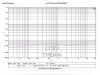
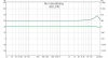
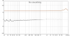
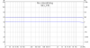
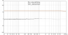
That frequency response analysis is meaningless for me on this to begin with. I just wanted to show 2 DACs can have difference. Not that I can get the same results with Amir.
I can understand you. But you should not give up too early, it's real fun to dig into a unit's performance.

However if you want to show differences between DACs you have to make sure that your ADC is good enough for this purpose. Therefore it makes sense to measure a DAC with known excellent performance so you can compare your results with the known ones. This tells you the limits of your ADC, and then you know that you cannot get better results than your ADC alone delivers.

Now if you measure a DACs and it has at least 10 dB more distortion and noise than your ADC you know that this result is close to the real value. To prove that 2 DACs perform different at least one of them should have 10 dB more distortion and noise than your ADC. If both perform better than your ADC you can't say whether they are different or not.
 

chris0202

Member
Joined
Aug 7, 2019
Messages
46
Likes
6
I can understand you. But you should not give up too early, it's real fun to dig into a unit's performance.

However if you want to show differences between DACs you have to make sure that your ADC is good enough for this purpose. Therefore it makes sense to measure a DAC with known excellent performance so you can compare your results with the known ones. This tells you the limits of your ADC, and then you know that you cannot get better results than your ADC alone delivers.

Now if you measure a DACs and it has at least 10 dB more distortion and noise than your ADC you know that this result is close to the real value. To prove that 2 DACs perform different at least one of them should have 10 dB more distortion and noise than your ADC. If both perform better than your ADC you can't say whether they are different or not.

I have been playing with Deltawave for quite a while in cable measurement. I know what I am doing.

Some previous issues that poped up during discussion is mostly because I changed components and opamp in my D30. I did not mention as it is somewhat irrelavant to the purpose. The "clipping" that doesn't really exist at all is something related to Deltawave as it seems to have issues aligning recordings taken from topping and ud503 due to the D30 pop while playback started. Software suggests poor alignment and wanted to change algorithm, which resulted in some erratic results. But again, how does that affect different between 2 devices? I am positively surprised I was only accused to use "broken" recorders, not manipulating software settings.

Noise is not important to me. ENOB of 16 bit warrants low enough level that's hard to distinguish by ear, if I can get a different under such level, it is enough. However, it is disputable if difference under -100dB is not something one would worry about. With a speaker system it could be amplified enough to be heard. Application dependent.

So be it. Whatever I get out of this won't appear in a forum solderdude exists.
 
Last edited:

LTig

Master Contributor
Forum Donor
Joined
Feb 27, 2019
Messages
5,835
Likes
9,577
Location
Europe
I have been playing with Deltawave for quite a while in cable measurement. I know what I am doing.
Sorry to say, but that's your biggest problem. There are so many experts here who know a lot more than me so I would never say this except I'd be 1000% sure - and maybe better not even then.
[..]
Noise is not important to me. ENOB of 16 bit warrants low enough level that's hard to distinguish by ear, if I can get a different under such level, it is enough. However, it is disputable if difference under -100dB is not something one would worry about. With a speaker system it could be amplified enough to be heard. Application dependent.
Noise is important because it can hide distortion. But since it seems that you deliberately chose to ignore any advice given here I stop here. One can lead a horse to the trough but you can't force it to drink.
So be it. Whatever I get out of this won't appear in a forum solderdude exists.
Pity - really. He's one who gives very clear and understandable advice and never gets angry.
 

chris0202

Member
Joined
Aug 7, 2019
Messages
46
Likes
6
Pity - really. He's one who gives very clear and understandable advice and never gets angry.

It is good to know you like him. There are small circles around him and I came across some. Frankly I find myself hard to get useful information (apart from his opinion-directed technical approach, not the other way around. ) from him. Wavelength problem, perhaps. However nothing at lost, most of my questions were not new to the community and there are many other good sources of info around. At least most of the time I don't have to ask (as it was likely asked before) to get the answer.

I am logging myself out from all my devices to get to a new status, as my signature suggested.
 

BDWoody

Chief Cat Herder
Moderator
Forum Donor
Joined
Jan 9, 2019
Messages
7,082
Likes
23,532
Location
Mid-Atlantic, USA. (Maryland)
Frankly I find myself hard to get useful information (apart from his opinion-directed technical approach, not the other way around. ) from him. Wavelength problem, perhaps.

Well, given that he is one of the most helpful and patient members on the forum, maybe it isn't his wavelength that needs adjustment. If you're looking for better bedside manner, you aren't likely to find it. You also won't find him talking out of his ass. If he doesn't know something, he'll be the first to say so.

Maybe try again without feeling like you have to know everything, and you may learn something from him.
 

chris0202

Member
Joined
Aug 7, 2019
Messages
46
Likes
6
Since I do feel like smash this into the face of some smart Tech experts here who look at problems without thinking, I will post something I found out according to Pkane's advice.

First, there is no clipping. It turned out it is just UD503's RCA output doesn't like my recorder. Switched to XLR, it looked a lot better. RCA can feed into an amp without issue, but not this recorder. Blue is XLR, white RCA into the recorder.

503_xlr_rca.PNG

Second, regarding noise bump around 16kHz in my measurement. I check all power rail test points and near OPAMP power rail around the board with scope, nothing found. I then looked up in Topping website and they posted this THD+N vs freq. It turned out D30 was built to have rising distortion from 5Khz and onward, and my mod just showed the same issue. Both have 0.001% distortion at 16kHz. I will have to do a sinesweep to confirm similarity. Need another device for it due to driver issue.

d30_official_data.jpg

At last, my "corrected" result, despite there is barely anything anything to correct.

final result.PNG

Side note, this device can use the help of usb reclcker.

d30_jitter.PNG
 
Last edited:

cjm2077

Active Member
Joined
Jan 22, 2020
Messages
160
Likes
261
Since I do feel like smash this into the face of some smart Tech experts here who look at problems without thinking, I will post something I found out according to Pkane's advice.

First, there is no clipping. It turned out it is just UD503's RCA output doesn't like my recorder. Switched to XLR, it looked a lot better. RCA can feed into an amp without issue, but not this recorder. Blue is XLR, white RCA into the recorder.

View attachment 66463

That sounds a lot like clipping. What is it that it doesn't like? Did you try the same RCA out, but at 10 db lower out to see if that eliminated the spikes? That would indicate clipping was the issue.
 

chris0202

Member
Joined
Aug 7, 2019
Messages
46
Likes
6
That sounds a lot like clipping. What is it that it doesn't like? Did you try the same RCA out, but at 10 db lower out to see if that eliminated the spikes? That would indicate clipping was the issue.

I have reinterated many many many many times, no clipping. Entire recording session completed with same output level. Both XLR and RCA. Perhaps you only know it can be caused by clipping, but that's not true. I don't know real reason. My guess is impedance matching. The recorder only has 2K ohm input impedance, which is fairly low compared with many amps in the market.
 

cjm2077

Active Member
Joined
Jan 22, 2020
Messages
160
Likes
261
I have reinterated many many many many times, no clipping. Entire recording session completed with same output level. Both XLR and RCA. Perhaps you only know it can be caused by clipping, but that's not true. I don't know real reason. My guess is impedance matching. The recorder only has 2K ohm input impedance, which is fairly low compared with many amps in the market.

XLR usually uses higher input levels than RCA. If it has lower input impedance, how would it cause this issue without clipping? An impedance mismatch would still cause a level mismatch, which would have to cause clipping to get this result. Your explanation is just hand waving, you have to understand a process before you dismiss parts of it.

Did you try to reduce output by 10 dB and see if the spikes went away? Because that is how an engineer, or somebody who knew something about electronics, would try to eliminate a clipping issue.

(By the way, I'm just trying to help you in your problem solving process here. I have no attachment to any of the equipment you're talking about here, and I don't know you from a hole in the wall. I don't care what results you get. I just care that people solve problems scientifically.)
 
Last edited:

chris0202

Member
Joined
Aug 7, 2019
Messages
46
Likes
6
XLR usually uses higher input levels than RCA. If it has lower input impedance, how would it cause this issue without clipping? An impedance mismatch would still cause a level mismatch, which would have to cause clipping to get this result. Your explanation is just hand waving, you have to understand a process before you dismiss parts of it.

Did you try to reduce output by 10 dB and see if the spikes went away? Because that is how an engineer, or somebody who knew something about electronics, would try to eliminate a clipping issue.

Clipping was no issue. Source file the same with both devices, both dac output gain 0dB. Input level matched to -8dB on recorder. I can attach an amp to the RCA to lower distortion with exactly the same playback setup.

It’s really the time to stop thinking about clipping.
 

chris0202

Member
Joined
Aug 7, 2019
Messages
46
Likes
6
REW sinesweep with the aid of Realtek sound card. Not perfect, but useable. However don't expect I can get the same low THD measurement as Amir can achieve with a proper singal analyzer. All done with -30dBfs source file, no way of clipping as SPL live-checked and things almost all in phase.

No clipping detected by REW. I can see a similar bump from 5kHz as topping's offical measurement. During measurement I can see SPL meter rising near the end (~16dB rise near end), and it looks like Topping decided to bump up frequency response from 5kHz and on ward.

(Note that D30's output level is actually louder than 503 by 0.05dB. Check REW files. It is impossible that I clipped 503 but not d30. Clipping is an educated guess, but instsing that it happened is imagination.)

Those who think DACs sound the same, you are welcome continue to do so, but bear in mind that it is a religious belief. Some "Experts" only made it firmer, IMO.
 

Attachments

  • d30_official_data.jpg
    d30_official_data.jpg
    144.8 KB · Views: 74
  • d30_FR.png
    d30_FR.png
    15.8 KB · Views: 75
  • d30_distortion.png
    d30_distortion.png
    39.1 KB · Views: 80
  • 503_FR.png
    503_FR.png
    14.9 KB · Views: 74
  • 503.png
    503.png
    15.4 KB · Views: 73
  • rew.zip
    3.5 MB · Views: 71
Last edited:

solderdude

Grand Contributor
Joined
Jul 21, 2018
Messages
16,053
Likes
36,429
Location
The Neitherlands
Did you measure the FR of the D30 with the stock D30 or with the modified version ?
The peak you say is purpose made by Topping is not found in other measurements of the D30 and certainly not almost 10dB.
This is why someone (not me) mentioned peer review.
Is it entirely possible your mods f'ed up the response of the D30 or something else is in play ?
The UD503 measurement is plausible.

and it looks like Topping decided to bump up frequency response from 5kHz and on ward.
Could it possibly be measurement error or mods doing this instead of drawing conclusions based on errors on your side ?
IF Topping did what you say why would this not show in any measurements of other folks ?

Impedance mismatch is not an issue as there is no impedance to match at all. A load resistance could be too low. 2kOhm,certainly for XLR isn't a severe load at all and can easily be driven by any opamp out there. Besides, unless the input of the measurement device is transformer coupled it is unlikely to peak it's input level the way it is measured.
For this you will have to measure the input circuit of the measuring device. Use the UD503 for this + add resistors in the path to see if FR changes due to output resistance differences. Know the limits of test gear and its behavior is paramount. It should exceed performance of the DUT.

Why the USB reclocker remark ? At ASR you can only make such remarks when you have measured evidence the performance drastically improved using a reclocker.

Those who think DACs sound the same, you are welcome continue to do so, but bear in mind that it is a religious belief. Some "Experts" only made it firmer, IMO.
:D
 
Last edited:

chris0202

Member
Joined
Aug 7, 2019
Messages
46
Likes
6
Did you measure the FR of the D30 with the stock D30 or with the modified version ?
The peak you say is purpose made by Topping is not found in other measurements of the D30 and certainly not almost 10dB.
This is why someone (not me) mentioned peer review.
Is it entirely possible your mods f'ed up the response of the D30 or something else is in play ?
The UD503 measurement is plausible.

Impedance mismatch is not an issue as there is no impedance to match at all. A load resistance could be too low. 2kOhm,certainly for XLR isn't a severe load at all and can easily be driven by any opamp out there. Besides, unless the input of the measurement device is transformer coupled it is unlikely to peak it's input level the way it is measured.
For this you will have to measure the input circuit of the measuring device. Use the UD503 for this + add resistors in the path to see if FR changes due to output resistance differences. Know the limits of test gear and its behavior is paramount. It should exceed performance of the DUT.

Why the USB reclocker remark ? At ASR you can only make such remarks when you have measured evidence the performance drastically improved using a reclocker.

Ah, the worst Tech I have ever came across. OPA2134(stock), opa1656, and opa2111 all exhibit the same behavior. My mod doesn't touch resistor. Topping's resistors, however, have lower value than their color coding indicated, as I discovered after extracting two. That stopped me from touching them.

Unless my Mobo doesn't like D30, otherwise I see no reason it can mess it up consistently.
 

solderdude

Grand Contributor
Joined
Jul 21, 2018
Messages
16,053
Likes
36,429
Location
The Neitherlands
yeah yeah I know ... worst. bla bla bla.

But.. have you swapped opamps and measured ?
Have you undone ALL your mods ?
Have you compared to stock ?
Did you you measure/know the input characteristics of your ADC ?
How can you be sure the bump in FR is caused by Topping while no-one else has ever measured this ?
 

chris0202

Member
Joined
Aug 7, 2019
Messages
46
Likes
6
yeah yeah I know ... worst. bla bla bla.

But.. have you swapped opamps and measured ?
Have you undone ALL your mods ?
Have you compared to stock ?
Did you you measure/know the input characteristics of your ADC ?
How can you be sure the bump in FR is caused by Topping while no-one else has ever measured this ?

Have you any experience on this device? At least I got my hands on it. If you want to know something else than already posted, do your own test.
 

solderdude

Grand Contributor
Joined
Jul 21, 2018
Messages
16,053
Likes
36,429
Location
The Neitherlands
Is experience with a modified D30 essential for me to ask the questions which you refuse to answer ?
The D30 is measured countless times and your measurements deviate... and not a little but HUGE.
Why not consider something is 'wrong' other than the worst tech you ever encountered ?
 

Blumlein 88

Grand Contributor
Forum Donor
Joined
Feb 23, 2016
Messages
20,769
Likes
37,633
Is experience with a modified D30 essential for me to ask the questions which you refuse to answer ?
The D30 is measured countless times and your measurements deviate... and not a little but HUGE.
Why not consider something is 'wrong' other than the worst tech you ever encountered ?
If you are the worst tech chris0202 has encountered he must have had the best techs of anyone in the history of the world.

@chris0202 man as has been mentioned you appear to have little experience testing gear. Why not answer some questions that solderdude has asked, change some of your testing procedure, and it is obvious you WILL learn something. You aren't convincing anyone who knows much about this stuff. Back up, listen to suggestions, re-test and things can be straightened out. Maybe your D30 is faulty, if you'd listen to suggestions you'll be able to determine that too.

Not sure what your point is, but you aren't doing it any favors.
 

chris0202

Member
Joined
Aug 7, 2019
Messages
46
Likes
6
Why not consider something is 'wrong' other than the worst tech you ever encountered ?

Datasheet from opa134. THD+N rises sharply above 5kHz. I am surprised you think only I got it.

Did I measured opa2134(stock)? Yes. Is it the same? Yes. Did I changed anything parametrically? Yes, but only in PSU section. Did it caused problem? No, as scope real time FFT shows across all test points on the board, and opamp V+/V-.

I spent hours debugging almost everything you mentioned, it turned out all were false alarm. By far, all your questions missed. Statistically, on this problem, you are not performing well enough to convince me the other way.
 

Attachments

  • opa134 datasheet.PNG
    opa134 datasheet.PNG
    206.9 KB · Views: 89

solderdude

Grand Contributor
Joined
Jul 21, 2018
Messages
16,053
Likes
36,429
Location
The Neitherlands
Answer me this question.

You show a frequency response measured by you that has a +16dB peak AND shows phase shifts indicating a resonance.
ONLY you have measured this. The rest of the world hasn't.

You conclude 'and it looks like Topping decided to bump up frequency response from 5kHz and on ward' based on measurements that are either:
A: incorrect due to ... reason(s)
B: correct but caused by modifications you made.

What other conclusions can be drawn ?
 

chris0202

Member
Joined
Aug 7, 2019
Messages
46
Likes
6
Answer me this question.

You show a frequency response measured by you that has a +16dB peak AND shows phase shifts indicating a resonance.
ONLY you have measured this. The rest of the world hasn't.

You conclude 'and it looks like Topping decided to bump up frequency response from 5kHz and on ward' based on measurements that are either:
A: incorrect due to ... reason(s)
B: correct but caused by modifications you made.

What other conclusions can be drawn ?

C: topping has changed parts.

I removed these R from board with Vaccuum desoldering gun, and they measured 1.992kOhm (inside) and 1.799kOhms (outside). By color coding, they sound be 2.66kOhm and 1.86kOhm.

See, all assumptions based on me being wrong. And asked me to think alternaively. Fu...nny.
 

Attachments

  • resistor value.PNG
    resistor value.PNG
    1.3 MB · Views: 85
Top Bottom