• Welcome to ASR. There are many reviews of audio hardware and expert members to help answer your questions. Click here to have your audio equipment measured for free!

Relay Resistor Switch Networks for Audio Volume Control Operation and StuFF.

Doodski

Grand Contributor
Forum Donor
Joined
Dec 9, 2019
Messages
25,510
Likes
26,836
Location
Canada
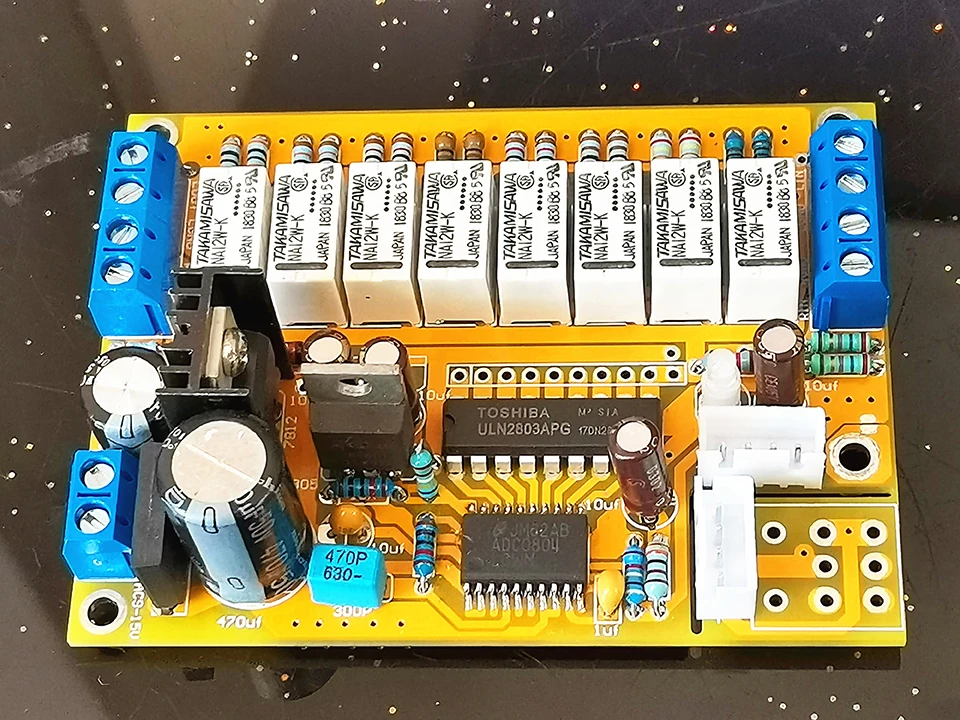
We are often seeing and commenting on relay controlled volume controls and some peeps including myself have no idea how they operate so here's a thread on them. Here is a audio volume relay attenuator with IR control for more reference.
feb08_slantview_800.jpg

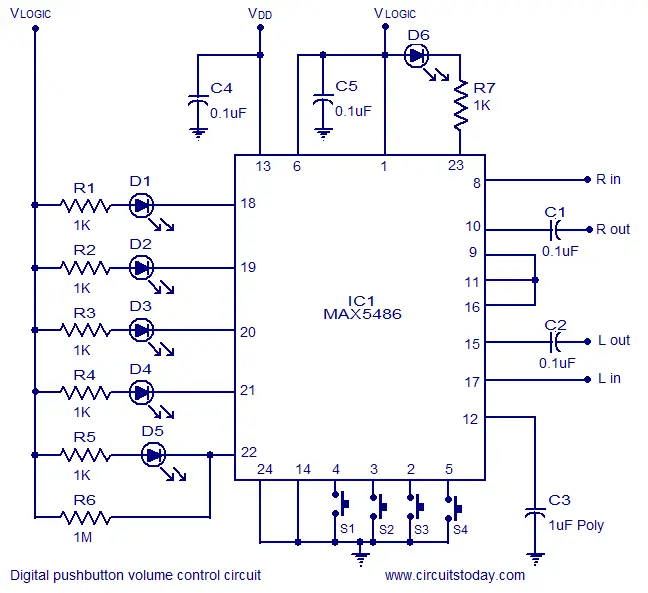
This circuit is similar to what is implemented in rotary-switch attenuators, and is in impedance behavior similar to a potentiometer.
potmeter16_cir.gif

Myself I am not sure how the relays are digitally switched and so discussion about that is welcomed. Ideas about resister types is good too. Any ideas are good.
 
You'll want to use Vishay S102 metal foil resistors .
 
Additional reference material for various circuit types.
digital-volume-control.gif

audio-stereo-switch.gif

This one is different. What is this thing? It was listed as a volume control.
Digital+Mains+Voltage+Indicator+Circuit+diagram.png

digital-volume-control-circuit.jpg

digital-volume-control-circuit.png
 
Last edited:
There's plenty of standalone types which use say an ADC-080 from NXP (8 bit A/D converter) and a single wiper pot. The 8 bit binary output simply drives the 8 relays, giving you 256 discrete levels.

Do you want a breakdown on each circuit you have presented?

The top one is a single channel up/down/mute CMOS switched level control operated via likely spring return toggles.
The second circuit is a sequential 4-1 input switcher, not a volume control.
The third circuit is not "different" or a volume control, it is a voltmeter!
The fourth is basically the top one, duplicated.
The fifth is a dedicated IC for volume.

Have a look at the schiit Freya S board:
1636425533541.png


7 relays per channel, so 2^7 (which is 128) steps, except instead of R2R, the resistor network is possibly weighted like a log pot law. Probably using a log pot read by an A/D line on the micro and the two drivers chips simply operate the associated relays if normal weightings.

Here's a standalone ADC-080 design:
1636425610122.png


Oh, and your top image is a 4 input switcher with a 64 level switched resistor attenuator that would need uP control by the look of it.

Here's another ADC-080 design that you stack up for as many channels as you want (even balanced +/- can have their own boards)
 
Last edited:
There's plenty of standalone types which use say an ADC-080 from NXP (8 bit A/D converter) and a single wiper pot. The 8 bit binary output simply drives the 8 relays, giving you 256 discrete levels.

Do you want a breakdown on each circuit you have presented?

The top one is a single channel up/down/mute CMOS switched level control operated via likely spring return toggles.
The second circuit is a sequential 4-1 input switcher, not a volume control.
The third circuit is not "different" or a volume control, it is a voltmeter!
The fourth is basically the top one, duplicated.
The fifth is a dedicated IC for volume.

Have a look at the schiit Freya S board:
View attachment 164284

7 relays per channel, so 2^7 (which is 128) steps, except instead of R2R, the resistor network is possibly weighted like a log pot law. Probably using a log pot read by an A/D line on the micro and the two drivers chips simply operate the associated relays if normal weightings.

Here's a standalone ADC-080 design:
View attachment 164285

Oh, and your top image is a 4 input switcher with a 64 level switched resistor attenuator that would need uP control by the look of it.

Here's another ADC-080 design that you stack up for as many channels as you want (even balanced +/- can have their own boards)
Thanks! That clears up a lot of questions that where running through my mind. The electronics core training (Newer version of the same textbook that we studied.) that I received in Canada doesn't really get into digital circuitry analysis like these circuits. They cover the digital fundamentals well but not this sort of stuff. One needs to study engineering I imagine to get those assets.
 
Why the metal foil type? No inductance?

Vishay bulk foil resistors are extremely good tolerance and good temp. coefficient (they don't vary much with temp changes). Below is an example of Vishay Z-Foil.. 0.005% tolerance and 0.2ppm/C...


There is just 1 big downside, they are extremely expensive. There are 24 resistors in the photo you show. That will csot ~$400.
 
IMHO, thin film SMD resistors with ~0.1% will do (many pple recommend Susumu). They cost around 20-30cents each. Also, use one that is as high power rating as possible to minimise temp change.
 
Just a bit more to add. Smd resistors are a bit harder to solder. They are also less tolerant to heat. May need a bit of practice (told me a while to elarn how to solder them).
 
Just a bit more to add. Smd resistors are a bit harder to solder. They are also less tolerant to heat. May need a bit of practice (told me a while to elarn how to solder them).
I've worked SMD PCBs quite a bit and am good with a iron and flux. Those little little resisters can be dicey for sure sometimes... lol. I've lost a couple along the way.
 
Back
Top Bottom