
Hi all, I am in the process of drafting and ordering my first PCB ever, and thought i would post it here for suggestions or important deficiencies before sending out to print in China.
This is a project I make for fun. I came across recently of that very cool project squeezelite-ESP32 that shows you how to build a squeezelite streamer around a ESP32 microcontroller.

 github.com
These things are tiny and i find fascinating that with one of them and a couple of cables you can build a fully working wifi and bluetooth streamer for less than 6 euros!

A raspberry pi zero looks gigantic besides this.
By coincidence, i am in the need of a streamer with a toslink output and i thought that for the money a spdif hat for my raspberry pi costs, i can build a squeezelite-ESP32 with toslink output and have a beer with the rest. And it works! I have it working attached to the programmer board that i got for it. As you can see, you just need to attach a toslink emitter to the power, ground and a gpio pin and you are in business! I still can't believe it.

Well what i need now is to have it working stand alone, without having to plug it to the programmer board. To achieve this, i want to make a small PCB with a voltage regulator based on AMS1117 (5V from a usb charger to 3.3V) and the possibility to add the toslink emitter and a spdif coax output. For the coax, it is necessary to bring down the voltage of the GPIO from 3.3 to 0.6V (as explained in the project github). I have not tried coax myself yet.
The PCB must fulfill the following:
1. that it is as small as possible, so i can glue the streamer to the back of the dac. My current draft is 18x65 mm.
2. the most important and difficult: That i can still insert the ESP32 in the programmer after soldering it to the PCB in case i need to flash it again.
3. versatile enough that i can build toslink and/or coax, that i can power it with 5V or leave the voltage regulator unpopulated and feed 3.3V directly
4. I also added 6 header pins to be able to use the two i2s ports that the ESP32 has (not necessary for the squeezeplayer project though)
What i think is the trickiest part is to be able to insert it in the programmer again. The programmer has "spring" pins that fit the two castellated sides of the ESP32. The only solution i can think of is making the pcb as thin as possible and 1 mm narrower than the ESP32 (that is, 17 mm wide instead of 18 mm). The problem in this case is how to solder it. I thought if i leave some holes coincident with some of the pads of the microcontroller, i can solder through the hole. I have no idea how this is going to work and that's why i am posting this here. Another option would be to be able to extract the module, but i cannot think how without making the pcb too big...
Other features are a header pin under the AMS1117 in case i need to skip it and use 3.3V source (i.e. a raspberry pi) and two header pins under the USB connector in the probable case that i don't manage to solder it (it is tiny) and i opt to just solder two cables or two header pin connectors. I left pin 1 disconnected not to short 5V to ground if i finally add the USB connector. i will solder the small bridge only if i use the header pins instead of the connector.
Well, long story short, this is the first time i use kicad, i had no clue of what a voltage regulator or a voltage divider was until this week, and the attached is where i am. Any advice is welcome. Note that i will only use 100 ohm resistors, i don't have other values.
These are the two very simple circuits on the board:
5V to 3.3V:
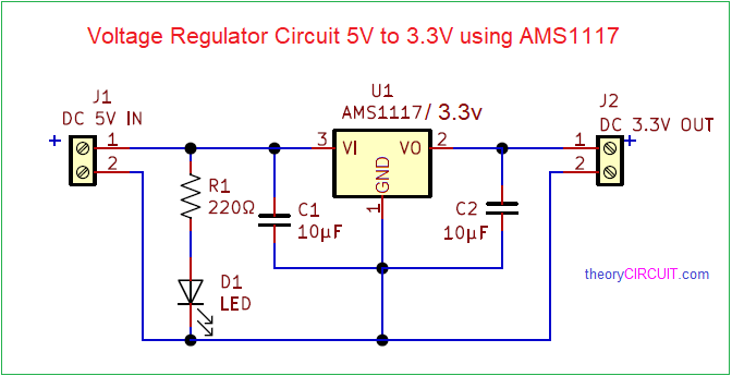
Somewhere i read that the ams1117 is more stable using 22uF condensers, but that goes far beyond my understanding, so i will give it a try with what i have (10uF) unless someone tells me i must use more than that... Could i use 2x10uF in parallel??
spdif coax connector:
100nF
GPIO ----210ohm-----------||---- coax S/PDIF signal out
|
110ohm
|
Ground -------------------------- coax signal ground
This is a project I make for fun. I came across recently of that very cool project squeezelite-ESP32 that shows you how to build a squeezelite streamer around a ESP32 microcontroller.
GitHub - sle118/squeezelite-esp32: ESP32 Music streaming based on Squeezelite, with support for multi-room sync, AirPlay, Bluetooth, Hardware buttons, display and more
ESP32 Music streaming based on Squeezelite, with support for multi-room sync, AirPlay, Bluetooth, Hardware buttons, display and more - sle118/squeezelite-esp32
github.com
These things are tiny and i find fascinating that with one of them and a couple of cables you can build a fully working wifi and bluetooth streamer for less than 6 euros!
A raspberry pi zero looks gigantic besides this.
By coincidence, i am in the need of a streamer with a toslink output and i thought that for the money a spdif hat for my raspberry pi costs, i can build a squeezelite-ESP32 with toslink output and have a beer with the rest. And it works! I have it working attached to the programmer board that i got for it. As you can see, you just need to attach a toslink emitter to the power, ground and a gpio pin and you are in business! I still can't believe it.
Well what i need now is to have it working stand alone, without having to plug it to the programmer board. To achieve this, i want to make a small PCB with a voltage regulator based on AMS1117 (5V from a usb charger to 3.3V) and the possibility to add the toslink emitter and a spdif coax output. For the coax, it is necessary to bring down the voltage of the GPIO from 3.3 to 0.6V (as explained in the project github). I have not tried coax myself yet.
The PCB must fulfill the following:
1. that it is as small as possible, so i can glue the streamer to the back of the dac. My current draft is 18x65 mm.
2. the most important and difficult: That i can still insert the ESP32 in the programmer after soldering it to the PCB in case i need to flash it again.
3. versatile enough that i can build toslink and/or coax, that i can power it with 5V or leave the voltage regulator unpopulated and feed 3.3V directly
4. I also added 6 header pins to be able to use the two i2s ports that the ESP32 has (not necessary for the squeezeplayer project though)
What i think is the trickiest part is to be able to insert it in the programmer again. The programmer has "spring" pins that fit the two castellated sides of the ESP32. The only solution i can think of is making the pcb as thin as possible and 1 mm narrower than the ESP32 (that is, 17 mm wide instead of 18 mm). The problem in this case is how to solder it. I thought if i leave some holes coincident with some of the pads of the microcontroller, i can solder through the hole. I have no idea how this is going to work and that's why i am posting this here. Another option would be to be able to extract the module, but i cannot think how without making the pcb too big...
Other features are a header pin under the AMS1117 in case i need to skip it and use 3.3V source (i.e. a raspberry pi) and two header pins under the USB connector in the probable case that i don't manage to solder it (it is tiny) and i opt to just solder two cables or two header pin connectors. I left pin 1 disconnected not to short 5V to ground if i finally add the USB connector. i will solder the small bridge only if i use the header pins instead of the connector.
Well, long story short, this is the first time i use kicad, i had no clue of what a voltage regulator or a voltage divider was until this week, and the attached is where i am. Any advice is welcome. Note that i will only use 100 ohm resistors, i don't have other values.
These are the two very simple circuits on the board:
5V to 3.3V:
Somewhere i read that the ams1117 is more stable using 22uF condensers, but that goes far beyond my understanding, so i will give it a try with what i have (10uF) unless someone tells me i must use more than that... Could i use 2x10uF in parallel??
spdif coax connector:
100nF
GPIO ----210ohm-----------||---- coax S/PDIF signal out
|
110ohm
|
Ground -------------------------- coax signal ground
Attachments
Last edited:
