There should really be a better formal guide to using VCAD as a pure sim tool, though Kimmosto has some very good guides for making driver measurements and using them in VCAD. I don't find this as helpful when determining which drivers to use. I'm gonna give you a quick walkthrough of my data sim workflow, because it isn't as easy as I'd like and took some time to come up with.
My usual workflow in VCAD is to start by setting up a bunch of folders. It's something like this:
<Project Name>
-->Driver Measurements
----><Driver1>
------>(Manufacturer Graph).png
------>(Frequency Response).frd
------>(Impedance).zma
----><Driver2>
...etc.
-->Box Simulations
----><DriverX>
------>(Vented Enclosure)
------>(Sealed Enclosure)
------>(Compact Enclosure)
...etc.
-->Merged Data
----><DriverX>
------>(Merged Measurements and Box Simulations)
...etc.
-->Diffraction Simulations
----><DriverX>
------>(An absolute pile of generated polar data)
...etc.
These folders are ordered top to bottom as the first to last simulation to accomplish.
1) Driver Measurements are done either with a mic or by using the SPL Trace in tools. I would save the FRD and ZMA data in separate folders for each driver.
2) I've already mentioned the Enclosure tool, but the value of the box sim cannot be overstated. You can save and restore different enclosure orders, driver arrangements, whatever. It's the best tool. But it does not replace actually constructing a box and measuring it.
3) In Tools, there is also the Merger. You will want to merge your "Far" driver measurements with your "Near" box sims. Don't forget to include the impedance from the box, as it will affect everything down the line. These should be exported in preparation for the next step. There's a lot of guesswork here, so don't take it too seriously. Any minute details under 500hz won't matter once the sound hits the room anyways.
4) The most important tool after box simulation is the front baffle. In many ways this a more important decision as it geometrically restricts the remainder of your enclosure choices. This also breaks a lot of driver arrangements. I recommend calculating each driver separately, even if they are an "array", like in an MTM or TMWW, as I find it better simulates impedance, cancellations, and diffraction. This tool does not help with waveguides. Those need their own measurements. Remember to place the microphone icon at the center of each driver placement, and select "Full Space" after uploading the merged data. It's also helpful to have a CAD drawing of the baffle for reference/adjustment and the necessary data points for driver size. It will probably be difficult to simulate an isobaric correctly because of this, as they act like one driver.
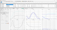
After that it's all crossover work. Don't forget to space each driver correctly to simulate dispersion. If you do it all right, it should look something like this:
View attachment 320038