To make a very long story short, I am making a DIY active 3 way speaker. The goal was to have something somewhat efficient, compact, and high fidelity. The speaker I chose for the low end was a dayton E150HE-44 subwoofer. What occured to me while designing this thing is I'm going to be putting a subwoofer into a fairly small enclosure. I've been looking up techniques in order to mitigate the effects of this (fighting physics is hard) and have come up with two: putting two of these woofers in isobar, and using motional feedback (MFB). My question is: is it possible, or practical really, to use these two things together?

-
WANTED: Happy members who like to discuss audio and other topics related to our interest. Desire to learn and share knowledge of science required. There are many reviews of audio hardware and expert members to help answer your questions. Click here to have your audio equipment measured for free!
You are using an out of date browser. It may not display this or other websites correctly.
You should upgrade or use an alternative browser.
You should upgrade or use an alternative browser.
MFB Isobaric
- Thread starter BKr0n
- Start date
- Thread Starter
- #3
I figured it's DIY. Can go overkill as you want (as long as you're willing to cry over your wallet after).Why use MFB and Isobaric? They‘re both corrective.
Nope. I do however have a background in electronics and a little bit of design as well. It's not like all the concepts are new to me, but I will admit there is a learning curve.Have you ever designed a speaker before? A compact isobaric accelerometer controlled 3-way is about as hard as possible for a first project.
"My enthusiasm will more than make up for my amateurism" I believe sums it up best

FYI - A designer talks about some the challenges with MFB for a small desktop sub here: https://audioxpress.com/article/r-d...ktop-subwoofers-for-nearfield-studio-monitors
Okay, the electronics background really helps. Otherwise I would've probably just dismissed you at this point, honestly. There's a ton to work on and VituixCAD is your friend. Honestly, starting from a sub-bass unit is a little weird, but it means you'll be working from that maximum SPL standpoint. So you'll have to calculate that. The box can be simulated in VCAD, including isobarics and multiple drivers in a single volumetric space. It can do a lot of ports and stuff.
You'll then have to find a midrange/midwoofer that can meet it, same with a tweeter. Matching dispersion and choosing a driver layout is hard and I suggest you google that. The front baffle will radiate and affect driver responses. Box design is a whole can of worms as a total volume in a formula vs six resonating panels. Essentially you need to tie each panel to each other in an effective way to quell resonance. Damping is a whole other bag of cats.
You should know more than I do already about crossovers if your electronics background is legit. 3-ways will have a ton of parts, a low-pass, a high-pass, a combo on the midrange, maybe some notches for leveling impedance... It can be a lot. Crossovers affect phase and will determine which parts of the driver's directivity applies to the speaker. This can include cancellations depending on the driver layout and your filter orders and your turbo encabulator. Getting dispersion to match and work (especially vertically) is the greatest challenge. The best distances (center-to-center) are 1/4-1/3 crossover wavelength. 6/5 is supposed to work as well.
A mic and some drivers are the best and most reliable way to build a speaker, and a multi-way DSP controller will definitely be the most effective turnkey solution, requiring no additional analog components in the system. A MiniDSP 4x8, Hypex FAxx3, or some competitor or equivalent will do wonders in an afternoon.
My last suggestion is to build the sub section in an opposed format, either cone-to-cone or magnet-to-magnet, so they can be run non-isobaric in a DOS format, or if the MFB is adequate for distortion control and extension. On the other hand, that Dayton seems designed to work with an available passive radiator, which can also be simulated in VituixCAD with a quick copy/paste from the loudspeakerdatabase.com and will similarly afford a lower fs without all the drawbacks of isobarics.
I'm sure the folks here and the friendly people at DIYAudio will be happy to help with specific questions.
Last edited:
Isobaric only halves the VAS, and due to the lower impedance (if parallel), you gain 3dB efficiency. All in all, that’s not very much for double the price. You may reduce distortion a bit, as well.
In current times it’s probably more efficient to just have the two woofers work together in the smaller box and pump some more power in the voice coils by DSP correction (Linkwitz transform for example). A few simple simulations will tell you.
And if you’re after efficiency, don’t build a closed box anyway.
- Thread Starter
- #8
This is great! Thanks for the link!FYI - A designer talks about some the challenges with MFB for a small desktop sub here: https://audioxpress.com/article/r-d...ktop-subwoofers-for-nearfield-studio-monitors
I've been fiddling around with VCAD a bit since the start of this. Still trying to figure out where everything is. I'm assuming it can do custom enclosures as well?There's a ton to work on and VituixCAD is your friend. Honestly, starting from a sub-bass unit is a little weird, but it means you'll be working from that maximum SPL standpoint. So you'll have to calculate that. The box can be simulated in VCAD, including isobarics and multiple drivers in a single volumetric space. It can do a lot of ports and stuff.
I was thinking about trying to integrate some sort of design from like a home DIY perspective. The "room within a room" idea kind of stuck out to me. I was thinking of something to the effect of creating a seperate enclosure for each speaker, and then seperating them with something really dense. I figure its probably way more important segragating the bass frequencies from the mid/hi than vice versa.You'll then have to find a midrange/midwoofer that can meet it, same with a tweeter. Matching dispersion and choosing a driver layout is hard and I suggest you google that. The front baffle will radiate and affect driver responses. Box design is a whole can of worms as a total volume in a formula vs six resonating panels. Essentially you need to tie each panel to each other in an effective way to quell resonance. Damping is a whole other bag of cats.
Attached is the filter I have so far. It's a state variable filter with a LR4 curve3-ways will have a ton of parts, a low-pass, a high-pass, a combo on the midrange, maybe some notches for leveling impedance... It can be a lot.
I downloaded LTspice and have been fiddling with turning it into a full differential circuit.does that go next to the flux capacitor?turbo encabulator
I originally wanted to do this digital, but the design would have been far more expensive, and my programming skills are not fantastic.and a multi-way DSP controller will definitely be the most effective turnkey solution
How would a passive radiator help in this situation? I don't have a lot of experience with them...My last suggestion is to build the sub section in an opposed format, either cone-to-cone or magnet-to-magnet, so they can be run non-isobaric in a DOS format, or if the MFB is adequate for distortion control and extension. On the other hand, that Dayton seems designed to work with an available passive radiator, which can also be simulated in VituixCAD with a quick copy/paste from the loudspeakerdatabase.com and will similarly afford a lower fs without all the drawbacks of isobarics.
The speakers themselves I was going to run at low power. I'm still fiddling around with the mid/hi section, but the power section I'm looking into will probably be a TPA3255. Efficient power delivery and it has good distortion figures. That should probably be more than sufficient to drive both subs.In current times it’s probably more efficient to just have the two woofers work together in the smaller box and pump some more power in the voice coils by DSP correction (Linkwitz transform for example). A few simple simulations will tell you.
Attachments
-
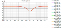 corrected svf lr4 Directivity (hor).png16.6 KB · Views: 32
 -
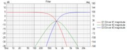 corrected svf lr4 Filter.png20.5 KB · Views: 35
 -
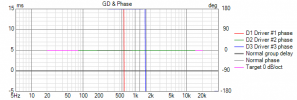 corrected svf lr4 GD+Phase.png13 KB · Views: 32
 -
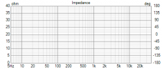 corrected svf lr4 Impedance.png9.7 KB · Views: 37
 -
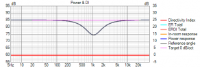 corrected svf lr4 Power+DI.png14.3 KB · Views: 28
 -
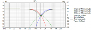 corrected svf lr4 SPL.png20.5 KB · Views: 37
 -
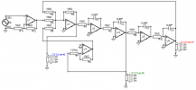 corrected svf lr4 XO-schema-1.png15.7 KB · Views: 34
I built my first isobarics in the early 1980's. Here are a few observations:
1. Isobarics have better low-end than is predicted by a halving of effective Vas (this according to measured response, not just subjective impressions). I speculate that the airmass inside the isochamber couples to the cones somewhat and increases the effective moving mass accordingly.
2. Isobaric configurations suck in the midrange, so imo it's generally not a good idea to use them up into the midrange region. I think the issue is that as the wavelengths become shorter the inner woofer is no longer equalizing the pressure inside the isochamber, and you end up having effectively double the midrange energy bouncing around inside the isochamber relative to the output from the front of the outer woofer. This is not the sort of problem EQ can fix.
3. The isochamber is small and therefore more susceptible to heat build-up than a normal-sized woofer airspace would be, assuming one or both woofer motors are within the isochamber.
4. The outer woofer's excursions can be pretty large because the inner woofer's function is to reduce the backpressure on the cone. The woofer you've chosen does have exceptional x-max, but just be aware that you're more likely to tap the voicecoil against the backplate with an isobaric, or at least with a sealed isobaric, configuration. Vented isobaric probably not so much, assuming a protective highpass filter below the tuning frequency.
If you're planning to push that woofer fairly hard my suggestion would be a vented enclosure, as this reduces the excursion and power required for a given F3 AND allows for an exchange of air with the outside world, which is beneficial from a thermal management standpoint. I haven't run any simulations but my guess is that the required port length might not fit inside the enclosure, BUT if the speakers are going on stands you may be able to hide the port inside the stand.
Last edited:
Why would you make an analog active filter? Even if you would, this is totally pointless without measurements of the drivers in the box.
I have no idea what you just said or what that circuit is doing. Crossovers are my weakness. Good luck.Attached is the filter I have so far. It's a state variable filter with a LR4 curve
By allowing the rear wave to act on another diaphragm better suited for lower frequencies. This is the smallest and often cleanest way to extend a woofer’s bass without electronics or vents. A good one will be designed with a specific driver and use case in mind, like that Dayton driver. A vent will be cheaper, but adds the issue of turbulence.How would a passive radiator help in this situation? I don't have a lot of experience with them...
In “Tools” there is an enclosure window, equal in power to VCAD’s main window for optimizing bass. You can sim vents, sealed systems, driver arrays, isobarics, passive radiators, added mass, and simulate excursion, turbulence, and power handling with EQ/circuitry.I've been fiddling around with VCAD a bit since the start of this. Still trying to figure out where everything is. I'm assuming it can do custom enclosures as well?
The real problem with isobarics, IMO. They are for cheap stuff with no range and stupid high end custom stuff with extreme power handling.All in all, that’s not very much for double the price.
- Thread Starter
- #12
While the sub can go into the midrange, I'll be cutting off at about 300Hz and let the actual mid driver take care of the rest.Isobaric configurations suck in the midrange, so imo it's generally not a good idea to use them up into the midrange region.
I guess that brings up a good question: are isobaric speakers uni or bidirectional in their "use" of sound?4. The outer woofer's excursions can be pretty large because the inner woofer's function is to reduce the backpressure on the cone. The woofer you've chosen does have exceptional x-max, but just be aware that you're more likely to tap the voicecoil against the backplate with an isobaric, or at least with a sealed isobaric, configuration. Vented isobaric probably not so much, assuming a protective highpass filter below the tuning frequency.
Not too hard if I can help it. The main thing is it's about 10db shy on sensitivity compared to the mid/hi, but I'm only probably going to be running those at either 10 or 20 watts at most.If you're planning to push that woofer fairly hard my suggestion would be a vented enclosure, as this reduces the excursion and power required for a given F3 AND allows for an exchange of air with the outside world, which is beneficial from a thermal management ststandpoint.
I thought one of the main selling points of isobaric is it didn't need as much space? Also that's a cool idea I didn't even think to use the stand like that.I haven't run any simulations but my guess is that the required port length might not fit inside the enclosure, BUT if the speakers are going on stands you may be able to hide the port inside the stand.
Because digital the way I wanted to do it is too expensive and I'm not the greatest programmer. Although you do have a point. Maybe I should try building the enclosure before I work on the amp design...Why would you make an analog active filter? Even if you would, this is totally pointless without measurements of the drivers in the bbox.
Alright that makes sense. So would I need to port it as well, or just use the radiator?By allowing the rear wave to act on another diaphragm better suited for lower frequencies. This is the smallest and often cleanest way to extend a woofer’s bass without electronics or vents. A good one will be designed with a specific driver and use case in mind, like that Dayton driver. A vent will be cheaper, but adds the issue of turbulence.
Cool thanksIn “Tools” there is an enclosure window, equal in power to VCAD’s main window for optimizing bass. You can sim vents, sealed systems, driver arrays, isobarics, passive radiators, added mass, and simulate excursion, turbulence, and power handling with EQ/circuitry.
- Thread Starter
- #13
What makes a closed box inefficient?And if you’re after efficiency, don’t build a closed box anyway.
Then maybe do it another way?Because digital the way I wanted to do it is too expensive and I'm not the greatest programmer.
That’s not just a maybeAlthough you do have a point. Maybe I should try building the enclosure before I work on the amp design...
you’ll be wasting a lot of time otherwise and won’t get the result you’ll want.Also note that these simple filters will not correct any other frequency response anomalies like resonances and diffraction effects. For every correction you need a bunch more components, adding cost and complexity.
It’s either one or the other. And remember that you’ll need about twice the SD for a PR.Alright that makes sense. So would I need to port it as well, or just use the radiator?
Last edited:
Well, after open baffle its basically the least efficient way of making bass. A resonant system like reflex or passive radiator is simply more efficient until it’s tuning. The trade-off is that it’s not below it. Usually it’s also lower distortion.What makes a closed box inefficient?
just use the radiator
- Thread Starter
- #17
The way I wanted to do it is relatively simple in theory, just not execution. Sharc project board, and make a dac/adc board for it. I'm just not great with SPI and I wanted to use SAR dac/adc. From my understanding, that's a lot of code, even with sigmastudio.Then maybe do it another way?
What would be a good place to start then on testing enclosure acoustics?That’s not just a maybe
Also note that these simple filters will not correct any other frequency response anomalies like resonances and diffraction effects. For every correction YouTubers a bunch more components, adding cost and complexity.
Why would you want to do that then? I doubt there is any advantage in using these kind of ADCs for audio. DACs and ADCs for audio are a solved problem, no point in using some exotic stuff.I wanted to use SAR dac/adc. From my understanding, that's a lot of code, even with sigmastudio.
Start by simulating as far as you can, then actually building the stuff and measuring. Then based on the measurements you can create the filters.What would be a good place to start then on testing enclosure acoustics?
- Thread Starter
- #19
It's not so much the DACs (those are actually pretty good for audio) as the ADCs. Noise figures are way better on SAR than on delta sigma (typically). That and, when it comes down to it, it's still taking data from the analog domain and converting into the digital and vice versa. I would imagine you would want that to be as precise as possible. You're also looking at about the same price when it comes to those DACs (sabre dacs etc). The ADCs are more expensive, but that's also because you're looking at chips that are typically used for test equipment. That's also why they typically run off of SPI as opposed to I2C or I2S or any other SPORT. So audio DACs? Sure. ADCs? Not so much. Even then there's still no autopilot for telling the chips to talk to eachother.Why would you want to do that then? I doubt there is any advantage in using these kind of ADCs for audio. DACs and ADCs for audio are a solved problem, no point in using some exotic stuff.
Sounds easy enough. Any program in particular I should look into or should VCAD cover it?Start by simulating as far as you can, then actually building the stuff and measuring. Then based on the measurements you can create the filters.
I doubt you can make anything better than something like an E1DA Cosmos. What do you have connected in the analog domain that needs so much SNR anyway? A normal audio ADC will do just fine. It does for all the recorded audio you already play every day, so will be good enough for you as well.It's not so much the DACs (those are actually pretty good for audio) as the ADCs. Noise figures are way better on SAR than on delta sigma (typically). That and, when it comes down to it, it's still taking data from the analog domain and converting into the digital and vice versa. I would imagine you would want that to be as precise as possible.
Sure, give that a try. I’ve never mastered it, I use the relatively ancient BoxSim. Mostly because I know it much better. VCAD should give more accurate results I assume.Sounds easy enough. Any program in particular I should look into or should VCAD cover it?
Similar threads
- Replies
- 4
- Views
- 565
- Replies
- 68
- Views
- 8K