• WANTED: Happy members who like to discuss audio and other topics related to our interest. Desire to learn and share knowledge of science required. There are many reviews of audio hardware and expert members to help answer your questions. Click here to have your audio equipment measured for free!

JBL VRX932LAP Amp - Power flickering on and off in rapid succession

OP
B

beavernuggetz

Member
Joined
Sep 21, 2023
Messages
36
Likes
2
You know what's odd? Yesterday I spent some time taking measurements again and it was dead; today I went in to measure voltage between SMPSREF & R40/641 and it measured 29 volts, shut it off to avoid cooking R610, applied power again after it cooled off, and the darn thing powered on. What gives?

Anyway, here are my findings from your questions.
V or mV? 10 V would indicate a major short
Measured again; it is closer to 9.5 volts across all 3 resistors. The current limiter bulb does not indicate any type of short and the only thing getting hot as before is R610.

These guys (R640/641) ought to be directly in parallel.
You are correct, I did not measure properly; they both have 12.2 volts across. They also measure 1.35K resistance.

Here is the thing though, before soldering TL494 & FAN7380MX the voltage between SMPSREF & D605 was very close to 16 VDC which I thought was enough to power up the amp but unfortunately that was not the case.

Again, I'm clueless but happy that it's working; hopefully it stays this way.

You may have better insight as to what could have brought this thing back to life if nothing has changed.

PS: I did add one additional screw to hold the board down (since I'm only testing at this stage only a few screws are used) near the power supply side so perhaps the PCB was not grounded properly.

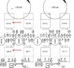
Here is a picture denoting where continuity exists.

1d6487b880a5.jpg
 
Last edited:
OP
B

beavernuggetz

Member
Joined
Sep 21, 2023
Messages
36
Likes
2
It did not last unfortunately and it is back to being dead.

Voltage between SMPSREF & R40/641 shows 29 volts.
Voltage across R637/638/639 still shows up as ~10 VDC.
Voltage between SMPSREF & D605 is back down to 6.5.
 
OP
B

beavernuggetz

Member
Joined
Sep 21, 2023
Messages
36
Likes
2
Okay, feels like I'm having a conversation with myself but here is the latest update.
R637/638/639 which have a marking of "X10" on them were reading extremely high resistance (0.5MΩ).
On the working boards, these measure 10 Ohms but different calculators and websites come back with a value of 24 Ohms.
Replaced all 3 with 24 Ohm resistors and now the amp powers on but immediately goes into that clicking on/off in rapid succession status as the original amp; the power indicator light matches the clicking.
Could this issue be related to the 24 Ohm resistors, are they supposed to be 10 Ohms instead?
 

AnalogSteph

Major Contributor
Joined
Nov 6, 2018
Messages
3,395
Likes
3,343
Location
.de
The schematic sure says 10 ohms, but I'd say it should generally work with those, too.

Since all 3 were toast, you may have a short that's killing them, so I'd say measure voltage drop and try to find where that potential short is. Looks like the SMPS may be starting up but falling over or something. What of the ICs and driver circuitry is currently installed? This is one of those times where a thermal camera might come in handy...
 
OP
B

beavernuggetz

Member
Joined
Sep 21, 2023
Messages
36
Likes
2
Yes, the label on the resistors should be read as "10X' instead and they are definitely 10 Ohms.
I'll replace them again today with the proper ones and see if that makes any difference.
At this point everything is installed including TL494 & FAN7380MX.
Will use a thermal camera and see if anything is getting hot as well.
Can you please elaborate as to what you mean by voltage drop testing? My understanding is testing in 'Diode' mode but which components specifically?
 
Last edited:

AnalogSteph

Major Contributor
Joined
Nov 6, 2018
Messages
3,395
Likes
3,343
Location
.de
Sorry I wasn't being more clear, I wrote my last post in a bit of a rush. I meant measure voltage drop across your just-replaced resistors (in voltage mode, though it wouldn't matter much here), so you get an idea of the current flowing. It may be quite jumpy, but I suppose you won't have an oldschool analog voltmeter at hand.

For another theory, maybe the 30 V regulator gets shut down (check voltage across R645) without enough current being able to pass via D610 - R642. R642 is only a 1/4 W 10 ohm, and if there was enough current to mess up R637-39, it may very well have sustained damage as well. Make sure D610 is not shorted.
 
OP
B

beavernuggetz

Member
Joined
Sep 21, 2023
Messages
36
Likes
2
Thanks for the detailed explanation.

I don't have an analog meter but do own an oscilloscope if that's an option here. Will do the measurements and report back with the findings.
 

AnalogSteph

Major Contributor
Joined
Nov 6, 2018
Messages
3,395
Likes
3,343
Location
.de
I don't have an analog meter but do own an oscilloscope if that's an option here.
Not likely, unless it is the portable (battery-powered) variety or you have a differential probe, or the whole amp is on an isolation xmfr. Remember you're on the primary side there.
 
OP
B

beavernuggetz

Member
Joined
Sep 21, 2023
Messages
36
Likes
2
I do have it hooked up (the oscilloscope that is) to an isolation transformer so it should be safe. The amp is still connected to the current limiter light bulb fixture. Should be safe, right?
 

AnalogSteph

Major Contributor
Joined
Nov 6, 2018
Messages
3,395
Likes
3,343
Location
.de
As Dave explains in the above video, it's the DUT that should be hooked up to the isolation transformer, not the scope. This way the scope with its exposed connectors (and traditionally, a metal case) always remains firmly connected to PE and as such safe to touch. If you float the scope, you may receive a nasty shock depending on what you are probing on the primary side.
 
OP
B

beavernuggetz

Member
Joined
Sep 21, 2023
Messages
36
Likes
2
Here are some new details as requested.

First of all, the amp is not actually clicking on and off like the first one (where it was obvious that the relay was making the clicking sound) but rather the power indicator is pulsating/flickering on/off but the amp does not restart or power off while it's doing this. I do have a video if you'd like to see it. At this point, the only thing getting hot is R610 as previously stated.

I did go back and replaced R637/38/39 with 10Ω resistors; also replaced D607 and neither made any difference.
These 3 resistors are now measuring very low volts across; average of 0.001.

Voltage measurements
For another theory, maybe the 30 V regulator gets shut down (check voltage across R645) without enough current being able to pass via D610 - R642.
This seems very accurate. Voltage across R645 only goes up to 0.5 while D610 jumps between 22 to 24 volts.

Make sure D610 is not shorted.
D610 measures like a normal diode (only shows reading in one direction); also compared it to one on the working amps and it's the same.
Voltage wise, it jumps between 22 to 24 as mentioned before.

R642 is only a 1/4 W 10 ohm, and if there was enough current to mess up R637-39, it may very well have sustained damage as well.
R642 is also reading as 10Ω and has very low voltage flowing across it; between 0.129 and 0.270 VDC.

I have the parts, should I replace R642, R645, and D610?
 
Last edited:
OP
B

beavernuggetz

Member
Joined
Sep 21, 2023
Messages
36
Likes
2
Okay, I figured out what the issue was.

One or more of the 4 high voltage transistors labelled MPSW42 (Q607-610) were shorted; after replacing all 4 the amp now works like a champ.

@AnalogSteph, I will always be indebted to you for your time, sharing knowledge, and for helping me understand and learn about schematics, etc.

For anyone who may have similar issues in the future, this thread will be extremely helpful with great documentation.

Again, thank you so very much.
 
OP
B

beavernuggetz

Member
Joined
Sep 21, 2023
Messages
36
Likes
2
Happy new year @AnalogSteph

This is what I PM'd you about. Can you kindly check on this and let me know where I should focus, please?

Abnormal Voltage Readings:
Between SMPSREF & R642 - 12~14 on one side and 12~15 on the other.
Between SMPSREF & Q610 (facing flat side): Each leg measures between 12~16 volts.
Between SMPSREF & R610 - 310 on one side and ~15 on the other leg.
D606 across measures 14~16 volts.
D607 across measures 12~14 volts.
R640 & R641 - With negative facing D607 are getting almost nothing; 0.5 volts at most.
Relay is not clicking on.
R610 is the only component getting hot.

Normal Voltage Readings:
C610 & C611 (320 ish) with R603 & R604 showing approximately 160 volts each.
255k Chain shows 110, 214, 320.
R637/638/639 have pretty much nothing across.

Other Normal Readings:
* There is continuity between 1 leg of C664 & SMPSREF.
* D608 & D610 measure like normal diodes.
* D606 & D607 have connectivity to C611/R604.
* Good connection between R656 + R610 + R603 (C610).
* R640 & 641 both measure 1.374 kOhm.

Parts Replaced:
Q607, 608, 609, 610 (MPSW42)
D606 & 607 Zener diodes
R610 & 612 resistors
IGBTs Q605 & 606.
FAN7380
TL494C
J1Y & K1Y transistors
10 Ohm SMD resistors close to IGBTs Q605 & 606.
 
Last edited:
OP
B

beavernuggetz

Member
Joined
Sep 21, 2023
Messages
36
Likes
2
More info after going over our previous discussions:
With C600 out, D607 has 13~14 volts across.
With Q611 out, D606 has 15~16 volts across.
Both diodes have been replaced: D606&D607.

Did more prodding and on the "cold" side there are 2 shorted Mosfets.
Q272 & Q273 which are parallel to each other are testing short in all directions.

FQP17P06
FQP30N06


Perhaps this is the reason why the amp won't power on.
 

Attachments

  • Shorted.jpg
    Shorted.jpg
    77.7 KB · Views: 17
Last edited:

AnalogSteph

Major Contributor
Joined
Nov 6, 2018
Messages
3,395
Likes
3,343
Location
.de
I'm baaaack. :cool:
Did more prodding and on the "cold" side there are 2 shorted Mosfets.
Q272 & Q273 which are parallel to each other are testing short in all directions.

FQP17P06
FQP30N06


Perhaps this is the reason why the amp won't power on.
This would give you a direct short between +VCC and -VCC, so no wonder the power supply is unhappy. (They are not in parallel but in fact form a half-bridge.) This is your first blown output stage among these amps, I think? They know how to keep you on your toes.

You will need to inspect all the preceding parts in their driver circuitry to determine what may have caused them to fail (from the MOSFET gates right back to Q266/267). You should be able to test the rest of the amp after removing the shorted MOSFETs.
 
OP
B

beavernuggetz

Member
Joined
Sep 21, 2023
Messages
36
Likes
2
Glad to see you back. I should have tested all of these components before and not wasted so much time but that's how I learn; the hard way!

I'll definitely inspect all the other components around those 2 Mosfets including the path back to Q266/267 as suggested to see if there is any damage elsewhere.
 
OP
B

beavernuggetz

Member
Joined
Sep 21, 2023
Messages
36
Likes
2
Good news, the amp is back online after replacing the shorted Mosfets.
FQP30N06 is still available on Digikey.
FQP17P06 is no longer produced so used SPP18P06PHXKSA1 in its place with good results.
Just documenting it here for future reference.
Thanks again for all your help.
 
Top Bottom