• WANTED: Happy members who like to discuss audio and other topics related to our interest. Desire to learn and share knowledge of science required. There are many reviews of audio hardware and expert members to help answer your questions. Click here to have your audio equipment measured for free!

JBL VRX932LAP Amp - Power flickering on and off in rapid succession

OP
B

beavernuggetz

Member
Joined
Sep 21, 2023
Messages
36
Likes
2
Excellent stuff, tomorrow will check the other points you traced and move the jumper to that bigger spot attached to the thick trace instead as you suggested. Finally some progress with your fantastic help.
 
OP
B

beavernuggetz

Member
Joined
Sep 21, 2023
Messages
36
Likes
2
Alright, moved the jumper wire to the beefier trace as suggested and confirmed good connection between VPRI & R610/R612; also checked connection where you marked 'Jumper Wire 2 SMPSREF' and that connection is fine as well. Unfortunately I'm still only getting 4 VDC at D605. Any more ideas? I'm not sure how the voltage is supposed to travel to D605 after it leaves R610/R612 and or the 255K array.
 

Attachments

  • Jumper_Wire_0002.jpg
    Jumper_Wire_0002.jpg
    133 KB · Views: 37

AnalogSteph

Major Contributor
Joined
Nov 6, 2018
Messages
3,395
Likes
3,343
Location
.de
Unfortunately I'm still only getting 4 VDC at D605. Any more ideas? I'm not sure how the voltage is supposed to travel to D605 after it leaves R610/R612 and or the 255K array.
Via both regulators. We'll cross that bridge when we get to it.

Meanwhile, what are things like at D606 (which is the one actually fed by our resistor chain)? It should have about 30 V across it, and the anode should be firmly at SMPSREF (C611/R604).
Likewise, D607 should have about 17 V across it, and the anode should be firmly at SMPSREF.

If both diodes show elevated ground, have a look at the via carrying SMPSREF that pops up to the right of Q610.
 
OP
B

beavernuggetz

Member
Joined
Sep 21, 2023
Messages
36
Likes
2
Made a few measurements in 3 spots. Wasn't sure if you meant to measure voltage across the 2 legs of these diodes (excluding anode) or still referencing SMPSREF.

Anode is definitely connected to SMPSREF on all 3 and it was excluded when "measuring across" for voltages on these 3 components.

Q611 (measured by accident) has -23 volts across its legs.
D606 has 0 voltage across its legs but shows 23.74 between the one leg which sits alone on its top and SMPSREF.
D607 has 0 voltage across its legs but shows 4.7 between the one leg which sits alone on its top and SMPSREF.

Hopefully this makes some sense otherwise I'll explain it with a picture.
 

AnalogSteph

Major Contributor
Joined
Nov 6, 2018
Messages
3,395
Likes
3,343
Location
.de
Ah, I looked up the MMBZ52xxBLT1G diodes, and anode in this SOT-23 is the bottom left leg (1) and cathode is the middle top leg (3), with 2 being unused. Pesky SMD buggers. I was picturing the traditional through-hole type.

23.74 V across a 30 V zener is definitely not enough. 4.7 across a 17 V even less so, but let's not get ahead of ourselves.

What voltages referred to SMPSREF do you see on Q610? When facing the flat side, you should be seeing about 23.1 V, 23.74 V and ??? left to right (EBC pinout). (If you have trouble with the middle leg, go to the anode of D609 instead.) The right leg with our mystery voltage ??? should connect directly to the R610-R612 junction (aka VPRI). There should normally be a good portion of the primary voltage on there. Is this still 24 V as it was earlier? What's on the other side of R610 then? (There ought to be the full 320 V bulk voltage. As long as that's not the case you've got a problem and will need to figure out where it gets lost on the way from the bulk capacitor department.)
 
Last edited:
OP
B

beavernuggetz

Member
Joined
Sep 21, 2023
Messages
36
Likes
2
Hey @AnalogSteph, glad to see you back.

What voltages referred to SMPSREF do you see on Q610?
Facing the flat side, the following voltages are present: Right leg 23.53, middle leg 23.93, and right leg 23.24.

The right leg with our mystery voltage ??? should connect directly to the R610-R612 junction (aka VPRI).
Correct, voltage at R610 shows 23.60 volts.

Is this still 24 V as it was earlier?
Close to this.

What's on the other side of R610 then?
335.3 VDC.

Please let me know what else to check for; this one has become a huge mystery.
 

AnalogSteph

Major Contributor
Joined
Nov 6, 2018
Messages
3,395
Likes
3,343
Location
.de
I hope R610 is a 5 W type then, and even then it's going to be a toasty boi dissipating 4.03 W. That's 12.9 mA through it.

Let's see where that current is going. Please measure the voltage across all of:
1. R642
2. R640 or R641 and
3. R637/R638/R639
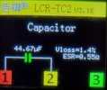
My bets are on the C600 / D607 area being suspect... if things don't change after removing C600, you may have a semi-dead D607 on your hands. It's normally dissipating around 150 mW (17 V * ~8.8 mA), which strikes me as a fair bit for a little SOT-23. It should still be within spec but would be expected to run somewhere around 100°C. Not any more now, of course.

Also, I seem to remember that you didn't see more than ~24 V anywhere in the 255k resistor chain? That's definitely not right. Things should also start out at 335 V there and go down in roughly 100 V steps.

What's puzzling me is that around 70% of the entire current budget (~12.5 mA) is being dissipated in D607. That leaves <4 mA going through the 15 V regulator, or around 50 mW to be dissipated. Well, it only has to be enough to start up the circuit until oscillation kicks in, so it would be enough for that I guess.
 
Last edited:
OP
B

beavernuggetz

Member
Joined
Sep 21, 2023
Messages
36
Likes
2
You are correct, R610 is definitely getting hot; saw it climb up to 160 Celsius. It's a 3W 25k Vishay PR03 but I am not sure how much heat it can handle. What's funny is that the original one seems even less appropriate to handle such heat and it was indeed discolored from the heat. Is this normal voltage for R610 or is there something going on with this amp which is feeding too much power into it? If necessary I can order 5W resistors.

Now, here are the measurements you requested; all with reference to SMPSREF:
R637/38/39 are all getting 4.189 volts.
R640 & 641: 4.738
R642: 22.82

255k resistor chain voltage with reference to SMPSREF::
R644: 24.09
R655: 126.3
R656: 337.8

Should I de-solder C600 to eliminate it from the equation? I can also do the same with D607 and test them both off the board and not in circuit.
 

AnalogSteph

Major Contributor
Joined
Nov 6, 2018
Messages
3,395
Likes
3,343
Location
.de
You are correct, R610 is definitely getting hot; saw it climb up to 160 Celsius. It's a 3W 25k Vishay PR03 but I am not sure how much heat it can handle. What's funny is that the original one seems even less appropriate to handle such heat and it was indeed discolored from the heat. Is this normal voltage for R610 or is there something going on with this amp which is feeding too much power into it? If necessary I can order 5W resistors.
I think the issue is that it normally only needs to dissipate that much for a split second until the power supply starts up. In normal operation it would be little more than a quarter of a watt.
Now, here are the measurements you requested; all with reference to SMPSREF:
R637/38/39 are all getting 4.189 volts.
R640 & 641: 4.738
R642: 22.82
I specifically wrote across and I did mean that (the point was using Ohm's law to determine the current through them). I guess the R640/641 measurement was on the side connecting to D607? (While you're in there, measure the resistance of R640|R641 with power off. Negative lead goes towards D607 so that the Q607-9 B-C junctions remain reverse-biased.)
255k resistor chain voltage with reference to SMPSREF::
Huh. That looks basically fine to me. Did we have measurements for Q611 or R645 yet? DC voltage across R645 should be under 0.4 V or so. Wasn't Q611 one you replaced because it was shorted? It's rated for 40 V of Vceo and basically a generic small transistor. You may end up having to test either D606 or Q611 out of circuit with a power supply good for at least 30 V, or just unsolder Q611 to see whether the problem persists.
Should I de-solder C600 to eliminate it from the equation?
That would have been the next thing I'd have suggested.
I can also do the same with D607 and test them both off the board and not in circuit.
That's definitely worth a shot. If D607 really can't sustain any more than 4 V, a multimeter diode test should generally show it.

I won't be entirely surprised if both D606 and D607 turn out to have issues. D607 is normally running a bit toasty anyway (~150 mW is a fair bit for a small part like that).
 
OP
B

beavernuggetz

Member
Joined
Sep 21, 2023
Messages
36
Likes
2
I think the issue is that it normally only needs to dissipate that much for a split second until the power supply starts up. In normal operation it would be little more than a quarter of a watt.
Okay, that makes sense and it's a relief to know.

I specifically wrote across and I did mean that (the point was using Ohm's law to determine the current through them). I guess the R640/641 measurement was on the side connecting to D607? (While you're in there, measure the resistance of R640|R641 with power off. Negative lead goes towards D607 so that the Q607-9 B-C junctions remain reverse-biased.)
Yes, you sure did so that's my fault. Measuring for DC voltage across R637/638/639 there is nothing; 0.0 volts. On the other hand, R640/641 read 17.70 across with negative facing D607. Resistance of R640/641 comes back as 1.373 kΩ.

Did we have measurements for Q611 or R645 yet? DC voltage across R645 should be under 0.4 V or so. Wasn't Q611 one you replaced because it was shorted? It's rated for 40 V of Vceo and basically a generic small transistor.
R645 measures 0 volts across it while Q611 (hasn't been replaced) measures 23.94 across and with reference to SMPSREF.

You may end up having to test either D606 or Q611 out of circuit with a power supply good for at least 30 V, or just unsolder Q611 to see whether the problem persists.
I have the power supply but don't know how to go about testing these components with it. I can definitely de-solder Q611. After doing so, what would you like me to check to see if the problem persists? Same goes for C600 & D607.

I won't be entirely surprised if both D606 and D607 turn out to have issues. D607 is normally running a bit toasty anyway (~150 mW is a fair bit for a small part like that).
I can definitely order replacements or try to find equivalents.

Hopefully this new info clarifies and answers your previous questions.
 

AnalogSteph

Major Contributor
Joined
Nov 6, 2018
Messages
3,395
Likes
3,343
Location
.de
Measuring for DC voltage across R637/638/639 there is nothing; 0.0 volts. On the other hand, R640/641 read 17.70 across with negative facing D607. Resistance of R640/641 comes back as 1.373 kΩ.
OK, so basically all the current is going into D607 || C600 then (12.89 mA according to Mr. Ohm).
I can definitely de-solder Q611. After doing so, what would you like me to check to see if the problem persists? Same goes for C600 & D607.
If C600 is out but you still only have 4 V and change across D607, the zener is clearly toast.
Ditto if things on D606 don't change with Q611 out.
 
OP
B

beavernuggetz

Member
Joined
Sep 21, 2023
Messages
36
Likes
2
With C600 out, D607 still shows 4.7 volts across.
With Q611 out, D606 shows 24 volts across.

Which ones would you replace? D606 & D607 for sure. What about C600 and Q611?
 
OP
B

beavernuggetz

Member
Joined
Sep 21, 2023
Messages
36
Likes
2
The capacitor seems okay; it's 47μF / 50 volts. I will order the Zeners and go from there.
 

Attachments

  • 2023-11-13 at 9.23.49 AM.jpeg
    2023-11-13 at 9.23.49 AM.jpeg
    204.1 KB · Views: 24
OP
B

beavernuggetz

Member
Joined
Sep 21, 2023
Messages
36
Likes
2
Here is a question. This is Amp #3.

After replacing all defective parts but without having the TL494 (Switching Controller) & FAN7380MX (High-Side Gate Driver IC) soldered on the PCB, turn the amp on and it immediately (after a couple of seconds) shorts the IGBTs. Without the IGBTs attached, I measured 16.70 volts between SMPSREF and the U1J diode which is normal and expected.

Any suggestions on what to check?
 

AnalogSteph

Major Contributor
Joined
Nov 6, 2018
Messages
3,395
Likes
3,343
Location
.de
In order to safely turn off the IGBT driver circuitry when the IC is not installed, FAN7380MX pins 7 and 6 should be connected together, as well as 5 and 4. If it still blows IGBTs under these circumstances (or +15V_CONTROL is dragged way down), either Q601 or Q603 would be highly suspect. Otherwise check R625/627 and connections in the area. R629-636 and C629-631 are all fine?

Shorting after a few seconds may also be an indication of underrated / counterfeit parts though. (Unlikely if you ordered from Digikey.)
 
OP
B

beavernuggetz

Member
Joined
Sep 21, 2023
Messages
36
Likes
2
This might be my fault; I followed this video where the guy shows the proper voltage between SMPSREF & U1J but it's clear now that the IGBTs were not soldered on the board when he did that. I'll check the Q601 & 3 as well as the resistors and caps you mentioned. Thanks again for all your help and I'll report back with the findings.
 
OP
B

beavernuggetz

Member
Joined
Sep 21, 2023
Messages
36
Likes
2
Hey, @AnalogSteph, I'm back after ordering and receiving the replacement parts for D606 & D607 for Amp #2.
Wanted to say you were 100% correct and that the amp worked once those two Zeners were replaced.
Amp #3 also worked after replacing the IGBTs and soldering both the TL494 & FAN7380MX before applying power to it.
Now on to Amp #4; will test voltage and report back.
Don't know how to thank you for sharing your awesome knowledge, skills, and time with me; I owe you so much.
 
OP
B

beavernuggetz

Member
Joined
Sep 21, 2023
Messages
36
Likes
2
So Amp #4 also wants to be difficult; there are only 6.5 volts between SMPSREF & D605.

Performed the same measurements as in the previous one and here are the results:
Voltage across R637/638/639 is approximately 10.
R640 shows 0 volts across it while R641 has 12.26; both come back with 1.3K resistance.
R642 & R645 have 0 volts across while Q611 shows 30 VDC.

255K Chain Voltage:
R644 = 128
R655 = 227
R656 = 331

R610 has 75 volts on one leg and 331 on the other with reference to SMPSREF.
Q610 measurements when facing flat side starting from right to left: Right has 70 volts, middle has 30.42 and left shows 29.73.
Q610 shows direct connection to R610/612 junction as well.

D606 has 30 volts across while D607 has 16.6.

What do you think?
 

AnalogSteph

Major Contributor
Joined
Nov 6, 2018
Messages
3,395
Likes
3,343
Location
.de
So Amp #4 also wants to be difficult; there are only 6.5 volts between SMPSREF & D605.

Performed the same measurements as in the previous one and here are the results:
Voltage across R637/638/639 is approximately 10.
V or mV? 10 V would indicate a major short (or more likely that they are toast, verify 10 ohms), 10 mV may well be normal.

What is voltage ref. SMPSREF at these?
R640 shows 0 volts across it while R641 has 12.26; both come back with 1.3K resistance.
?! These guys ought to be directly in parallel. Either you had bad contact on a probe when measuring or there's a bad connection of sorts that leaves one end of R640 dangling in thin air. Would you mind rechecking whether there is a bad connection between either end of R640 and Q607-9 collector / D607 anode (C600 +)? (It would be ironic if a bad joint from the factory had kept D607 alive...)

The rest of your voltages look sensible enough, I just don't know where between Q607-9 and D605 your +15V CONTROL is dropping that much.
 
Top Bottom