- Thread Starter
- #21
Will go offline now, will try to comment later this evening...
Sure, thank you for your comments so far!

Will go offline now, will try to comment later this evening...
I just did. Is it showing correctly now?
I can't see the picture. I could see the one in the previous post.


I'm at my office right now and some pictures / sites are blocked.
In your post #15 I could see it
Some people measure & flatten a frequency-dependant 1/3 octave windowed phase at LP and are very happy with it.
No, nothing after post #15, nothing before.
I need the pics to be hosted on ASR, like you did in that post.
https://www.audiosciencereview.com/forum/index.php?attachments/1554995881752-png.24733/
Thanks, I can see it now!
Well, the phase is pretty flat. You can even reduce the scale to +45 degrees / -45 degrees.
Now export the measurement, import it in RePhase, play the phase cursors with Q=1 and put it flat to 0 everywhere, especially in the 40 Hz - 200 Hz region.
Everything should be between +10 and -10.
Then listen. You should hear an improvement in the bass department (faster beats).
Don't over-correct. In that area, even a 10 degrees difference is audible. I experienced it recently.
I would advise you to try again.
For me, pre-ringing is still better than bass lasting forever anyway.
I would never say my bass with current filter settings is lasting forever, subjectively it sounds quite clean and "snappy". To be honest I am not sure I can hear the difference before I did phase correction and after that, which was not the case with correction of frequency response. On the other hand, I can easilly hear ringing and it sounds awful.
Is your microphone calibrated in amplitude and phase?
When trying to do room EQ measurements with REW you will find a lot of information on the Net. You have option to do RTA measurement with pink noise using moving microphone method. Another option is to make several sweeps at and around your LP and use "Average the response" feature under All SPL tab. If you want to preserve timing information you can rely on a single sweep or use Vector average (although that one tends to result in a weird frequency response, but there you have it).
However, with phase measurements things are getting a little tricky. let's assume for simpicity you have a done a single sweep and that it contains accurate info. You fixed the IR delay and your phase is shown wrapped in REW. But what now?
At the very beginning you will soon realise that it gets much harder to get phase response displayed correctly in REW as your distance between microphone and speaker gets bigger. If you measured from 10cm distance chances are you would not need to apply any gating and/or frequency dependent windowing to show pahse correctly.
If you measure from 0.5m or 2m you will probably need to make some adjustments under IR Window settings to get the phase displayed properly. But if you measure from your LP whivh is say 4 meters from your speakers and reflections in your room are pretty high you may realise that displaying phase correctly presents quite a challenge.
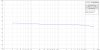
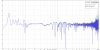
This is how it looks when I do it in my room with my left speaker, measured from app 2m, no gating:

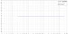
With right window of 3ms (doesn't display correctly with higher value):

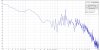
With FDW of 3 cycles (doesn't display correctly with higher value):

Here I would like to say that when I measure phase from 10cm no gating nor FDW is required to display phase correctly. As measuring distance increases the reflections are building up so I have to apply more and mroe gating to display phase.
Phase overlayed (3ms vs FDW 3cycl):

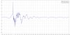
Step overlayed (3ms vs FDW 3cycl):

GD overlayed (3ms vs FDW 3cycl):

So, after all of these graphs a few question arises, like for example:
- what is the optimum distance to measure phase in your room? Very close to the speaker, say 10cm, or at your LP?
- what is the optimum way to adjust your measurement? Applaying right window time gating, FDW, or both?
- should we even bother with all this? Does getting the phase flat matters at all?
I would like to add here that, when i was doing manual correction of my room/speakers response I didn't rely much on measuring uncorrected phase response. Once I fixed amplitude response in rePhase I corrected phase of my filters so it would be as close to 0 as possible to stay minimum phase and I entered data about my crossover (LR 24dB/oct at 1800Hz) so the rePhase can take it into account. The graphs above are showing the results of that.
Or maybe the scales are off.
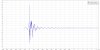
I tried to follow the instructions you provided on a random measurement (without EQ) I took a while ago (IR shift, 3ms right windowing) and these are the results. If I remember correctly the mic was approximately 1.5m away. Is the phase too good to be true or the internal DSP is doing a good job here? Or maybe the scales are off.
The speakers are LS50W and they have a "phase correction" feature that I normally keep turned on. They also have a high pass mode that's set to 80 Hz so I presume anything below 80 Hz is sent to the sub instead of Kefs.
Dogan
Looks fine, but also ^^^^^ this ^^^^^.
You're looking at things from 30,000 ft.
Set the range of the phase plot to +/- 180 deg, group delay to +/- 25 ms, and step response to -100 ms to +500 ms (or even much less!).
EDIT: would also not put much stock in the range < 300 Hz if your gate is 3 ms.