• WANTED: Happy members who like to discuss audio and other topics related to our interest. Desire to learn and share knowledge of science required. There are many reviews of audio hardware and expert members to help answer your questions. Click here to have your audio equipment measured for free!

Horn Speakers - Is it me or.......

... I've thought the old Klipsch Horns were the best of the old school horns in a proper corner in a large room. Better than Altec VOT's anyway. I was surprised when on 2 occasions I was able to EQ or Room correct some K-horns how much better it made them sound. Didn't diminish their dynamics, but did help their problems. ...
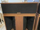
I love the sound of my Klipschorns (AK5, c. 2002 with Klipsch stock upgrade), in nearly airtight corners, with Audyssey Flat room correction plus tweeking with tone controls, a 4,500 cu.ft room with room treatment including painstakingly adjusted diffusion View attachment 389083 and absorption,
1724892755354.jpeg
1724892937981.jpeg

firm walls [(exterior panels, then 3/4" ply, 2X6 studs, glass wool, second layer 3/4 ply (staggered seams), and 5/8" Sheetrock, covered with rough plaster (except where it would hold K-horns out from the wall)View attachment 389083
 

Attachments

  • 1724898147119.jpeg
    1724898147119.jpeg
    210.6 KB · Views: 36
  • 1724899356193.png
    1724899356193.png
    190.3 KB · Views: 34
  • 1724902198222.jpeg
    1724902198222.jpeg
    73.7 KB · Views: 39
The big 15" JBLs (M2 and 4367) can, and the 4430 of yesteryear could. Earl Geddes' designs could, but they are no longer in production. The horn speakers in PBN's M-series can (not positive about the one with the giant butt cheeks horn; I'm not skeptical of it; just don't know enough about it). Synergy (Tom Danley) horns presumably can. I'm quite confident @Bjorn's speakers can. Probably the Dutch & Dutch 8c. The PiSpeakers 4Pi can. I'm sure there are others that don't come to mind offhand. I uses Earl Geddes' design principles (and sometimes Earl Geddes' math), so I claim that mine can.
Thank you!! Unfortunately all US Based - I'm looking for small horns in Europe, other than JBL (their looks are a problem).
 
M2 isn't particularly uniform, actually the design is clear step backwards in directivity compared to older JBL horns.

M2 horizontally (normalized):
JBL M2 (Crown iTech 5000 Amp; M2 Base Configuration) Horizontal Contour Plot (Normalized).png


Vertically:
JBL M2 (Crown iTech 5000 Amp; M2 Base Configuration) Vertical Contour Plot (Normalized).png


JBL 4430/35 looked a lot better but obviously driver quality at that time wasn't very good. No fancy sonogram graph back then.

polars.jpg


A horn with a 15" front firing woofer can certainly sound good. But it's fairly big step to a design with horn loading lower in frequency.

Small horns (smaller than about 50-60 cm) are not very good designs due to the loss of directivity and too high crossover IMO. If the size is a criteria, I would look at a different speaker design.
 
Small horns (smaller than about 50-60 cm) are not very good designs due to the loss of directivity and too high crossover IMO. If the size is a criteria, I would look at a different speaker design.
Thank you. Something like the JBL 4329P doesn't look that bad (https://www.erinsaudiocorner.com/loudspeakers/jbl_4329p/) doesn't it? I've the impression nothing else like the horn could give me this dynamic, liveliness, speed, attack :/
 
I've the impression nothing else like the horn could give me this dynamic, liveliness, speed, attack :/
Large horns with constant broadband directivity, low crossover and quality drivers. That's something entirely else than small JBL waveguides (waveguide=short horn with not that good loading). The latter is closer to traditional speakers IMO, and reaches more the ankle of big quality horns if you're lucky.
 
Thank you!! Unfortunately all US Based - I'm looking for small horns in Europe, other than JBL (their looks are a problem).

I recently listened to a most impressive pair of hORNS speakers, although I don't think they were set up for best imaging. I think they were PF10 Mk 3 or PG12 Mk 2 - stand-mounts that feature big bass drivers (10" or 12") and horn loaded top. They really did sound very good for their size. hORNS offer a wide range of horn speakers, although few UK dealers.


I recently listened to a most impressive pair of hORNS speakers, although I don't think they were set up for best imaging. I think they were PF10 Mk 3 or PG12 Mk 2 - stand-mounts that feature big bass drivers (10" or 12") and horn loaded top. They really did sound very good for their size. hORNS offer a wide range of horn speakers, although few UK dealers.


Thank you, their look is georgous! Just googled a couple of minutes, their frequency spectrum looks kind of strange: https://www.lenhifi.de/app/download/10176928171/AUDIO_Test_hORNS_FP_10.pdf?t=1598942182

The FP12 looks better

Unfortunately the only dealer in Germany is far away - but i put them on the list.
 
Thank you!! Unfortunately all US Based - I'm looking for small horns in Europe, other than JBL (their looks are a problem).

Maybe Zingali? Or Unison Research?

M2 isn't particularly uniform, actually the design is clear step backwards in directivity compared to older JBL horns.

M2 horizontally (normalized):
View attachment 389119

Vertically:
View attachment 389120

JBL 4430/35 looked a lot better but obviously driver quality at that time wasn't very good. No fancy sonogram graph back then.

View attachment 389123

Very interesting! To my ears the M2's horn sounded a bit bright, perhaps due to the horizontal off-axis "bumpage" from about 2k to about 7k.

A horn with a 15" front firing woofer can certainly sound good. But it's fairly big step to a design with horn loading lower in frequency.

Small horns (smaller than about 50-60 cm) are not very good designs due to the loss of directivity and too high crossover IMO. If the size is a criteria, I would look at a different speaker design.

I'm going to have to leave the 50+ cm size horns to other manufacturers, at least for now. I admire your work, but I'm not planning on trying to replicate it!
 
Waveguides and horns haven't been problem in few years now, anyone can roll their own, at any size and shape optimal for their own use case, with loading or not. See https://at-horns.eu/ and giant thread in diyaudio.com . Basically there is knowledge and parametrized math to come up with any shape and scripts to make BEM projects that run fast and one can churn out tens of versions a day with home computer trying to zone in. Yeah it's some work but it is possible to come up with a device with essentially flawless performance. Some available behind that link above.
 
Not too long after I first contacted Earl, he said to me (paraphrasing): "Duke, this speaker you want to build is something I've wanted to do for about ten years. Let's do this as a joint venture." The arrangement was that I'd pay for the stuff we needed and Earl would provide the engineering. Well I ran out of money had to drop out, so Earl finished the development of the Summa on his own. Then at one point I was assembling Summas for him at my home in New Orleans, but had to relocate unexpectedly, and no longer had a space where I could assemble and paint them.

Thanks so much for sharing that history! Really cool story.

My understand is that OS waveguides work well down to the 1000Hz zip code, but not so well any lower. Is that correct?
Another question if I may,....I find axisymmetric waveguides/horns tend not to measure so great directly on-axis, and I end up making the reference axis 10-15 degrees off.
Is that your experience with OS? (i'm having a bit of deja-vu, feeling like I already asked you this in the past...if so, pls pardon this forgetful old mellon :oops:)

In this post you can see a couple of photos from the early days of the Summa... the shoot-out speakers unveiled, and Earl and me at the Lone Star Audio Fest in 2005, which I think was the Summa's first foray into the outside world.

And you are absolutely correct, axisymmetric horns/waveguides have an on-axis anomaly that disappears about 10-15 degrees off-axis. What happens is, when you are right smack on-axis, there will be a frequency at which the (inevitable) mouth reflection arrives 1/2 wavelength behind straight-down-the-middle sound, causing a cancellation dip. The frequency of this dip depends in part on the microphone distance or listening distance because the geometry changes; the dip moves up in frequency as the distance increases. It would be a mistake to equalize this dip because in doing so you would be introducing an off-axis peak in that region throughout the room which will dominate the spectral balance of the reflected sound. (There may also be a smaller on-axis bump higher in frequency where the reflection arrives delayed by one wavelength.)

Earl optimized the response for 22.5 degrees off-axis, and I use anywhere from 15 degrees to 22.5 degrees depending on the specifics.

The kills-two-birds-with-one-stone solution to the on-axis dip is, to use a time/intensity trading configuration. The aggressive toe-in puts the center sweet spot about 15 degrees off-axis of each speaker.

The trade-off of this approach is, you lose the increased apparent source width (wider soundstage image) that you would normally get from the first same-side-wall refections. But in return you get a bit higher direct-to-reflected sound ratio and (imo more significant) a longer time delay imposed on the first strong lateral reflections, so image precision is increased and the strength of the "small room spatial signature" of the playback room is decreased.
 
Last edited:
And you are absolutely correct, axisymmetric horns/waveguides have an on-axis anomaly that disappears about 10-15 degrees off-axis. What happens is, when you are right smack on-axis, there will be a frequency at which the (inevitable) mouth reflection arrives 1/2 wavelength behind straight-down-the-middle sound, causing a cancellation dip.
Hi,
only if shape of the mouth makes diffraction, in other words waveguide curve changes abruptly enough and is not as good in this regard as it could be. Diffraction related secondary sound source can form at any point along the waveguide curvature but the curvature can be optimized so that this doesn't happen, including the mouth. The curvature starts from the phase plug essentially, continues through throat and to the mouth and could extend all the way to backside of the device. If you do this on-axis is as good as any other in this regards having practically no hint of diffraction related interference on-axis, or in any other axis. Although, on a freestanding waveguide diffraction at the low frequency where the waveguide size gets small relative to wavelength can be used to increase DI a bit, while higher than that stays clean. Tons of examples behind the links in my previous post. The first link contains several models you can go and buy and start 3D printing with small desktop printer within few minutes. Quite amazing actually. There is no need to get any legacy devices of yesteryear, unless one wants a legacy device, which many do, so, just trying to promote great work of Marcel Batik.
 
Last edited:
Hi tmuikku, I'm under the impression that Marcel also uses a reference axis that is offset from straight on-ax for all his sims. No?
 
Hi gnarly,

sometimes at least, but the 0-axis is still fine regarding the fear it not being any good.

Waveguides tend to beam top octave, perhaps even more than domes. Also, he has opted for rising DI in his waveguides, while lower DI is also possible, and I think he might compensate for these for visuals. And it's true, on-axis is quite easy to detect by ear just for very highs beaming, and due to many other issues like the diffraction. Top octave could also be optimized if driver exit wavefront was known, but this is something that is still lacking except with some particular drivers that happen to have it good. Hard to measure the wavefront from a driver as it is impedance tube stuff, and phaseplug is involved, and he is not there yet, perhaps in few years :) With ideal wavefront in simulator the top octave is also fine, especially if the wavefuide is brought all the way inside a 1" compression driver. Many drivers have exit section, so <1" diameter at phase plug.

In the end the systems in reality will have some wiggle here and there.

edit. bottom of this page has sim data, normalized to 5deg but on-axis is visible. If there was any wiggle it would show up in the graph.
 
Last edited:
Hi,
only if shape of the mouth makes diffraction, in other words waveguide curve changes abruptly enough and is not as good in this regard as it could be. Diffraction related secondary sound source can form at any point along the waveguide curvature but the curvature can be optimized so that this doesn't happen, including the mouth. The curvature starts from the phase plug essentially, continues through throat and to the mouth and could extend all the way to backside of the device. If you do this on-axis is as good as any other in this regards having practically no hint of diffraction related interference on-axis, or in any other axis. Although, on a freestanding waveguide diffraction at the low frequency where the waveguide size gets small relative to wavelength can be used to increase DI a bit, while higher than that stays clean. Tons of examples behind the links in my previous post. The first link contains several models you can go and buy and start 3D printing with small desktop printer within few minutes. Quite amazing actually. There is no need to get any legacy devices of yesteryear, unless one wants a legacy device, which many do, so, just trying to promote great work of Marcel Batik.

My understanding is that, in order to effectively avoid the mouth reflection in an axisymmetric device, a great deal of real estate has to be devoted to the round-over, and it has to be a full round-over, like the Le Cleac'h horns. Obviously it can be done at the expense of increased driver spacing and/or reduced effective mouth diameter, so imo it's a tradeoff.

My understanding is that Marcel's software is intended for the DIY community and I'm not a DIYer. But I'm not convinced there is significant improvement to be made over the Oblate Spheroid profile, assuming constant directivity with minimal disturbance of the wavefront is the priority.

I have not been favorably impressed with 3D printed horns thus far, but am waiting on a quote from a company who uses a technique that's significantly more advanced than desktop printing.

Waveguides tend to beam top octave, perhaps even more than domes. Also, [Marcel] has opted for rising DI in his waveguides...

I'm using a different approach to the issue of top-octave beaming, so I'd rather keep the DI as constant as I reasonably can for as long as I reasonably can, rather than gently increasing the DI (narrowing the pattern with increasing frequency) to intersect with the inevitable top octave beaming. (Top octave beaming is not inevitable with diffraction horns, but that's not what these are.)
 
Last edited:
My understanding is that, in order to effectively avoid the mouth reflection in an axisymmetric device, a great deal of real estate has to be devoted to the round-over, and it has to be a full round-over, like the Le Cleac'h horns.
An important thing to note regarding minimizing the axial response anomaly is that a section of a circular arc is not an ideal profile for the termination. Even with an impractically large radius, a significant reflection remains due to the abrupt change of curvature.

I used an angle- and curvature-matched section of an Euler spiral as the termination in my OS waveguide design. The axial ripple is not completely absent, but is pretty minor at about 2dB pk-pk. In contrast, a similarly sized OS waveguide with a 5 inch radius circular arc termination has an axial ripple of about 6dB pk-pk (according to simulation, at least).

Assuming a good termination, there's a tradeoff between DI flatness and axial ripple. In my design, I was targeting a flat DI more than the lowest possible ripple. As my measurements show, the DI is very flat indeed (±0.5dB from 1kHz to 15kHz) with the design axis set to 18°. Marcel's designs from the past couple years show that an axial ripple of effectively zero is possible at the expense of a somewhat more tilted DI.

My understanding is that Marcel's software is intended for the DIY community and I'm not a DIYer.
He said the following about a year ago:
I don't mind if people use my waveguides in their products, commercial or not, I can't do anything about it anyway, but please, at least mention my name when doing so. Thanks.
But I bet he'd be willing to work out some kind of agreement if you wanted to offer compensation.

I'm not convinced there is significant improvement to be made over the Oblate Spheroid profile, assuming constant directivity with minimal disturbance of the wavefront is the priority.
The ATH waveguides are still essentially OS near the throat.
 
I think a commercial loudspeaker is about to be launched, born of a collaboration project involving Earl and Marcel's work. Keep an eye on this link.

cheers
 
My understanding is that Marcel's software is intended for the DIY community and I'm not a DIYer. But I'm not convinced there is significant improvement to be made over the Oblate Spheroid profile, assuming constant directivity with minimal disturbance of the wavefront is the priority.
When I look at the response curves of that Marcel thread on diyaudio, I don't grasp what the objective was (and whether the curves show it achieves with spectacular success).
 
Last edited:
My understanding is that, in order to effectively avoid the mouth reflection in an axisymmetric device, a great deal of real estate has to be devoted to the round-over, and it has to be a full round-over, like the Le Cleac'h horns. Obviously it can be done at the expense of increased driver spacing and/or reduced effective mouth diameter, so imo it's a tradeoff.
Hi,
you are right the roundover needs real estate just like roundovers for any transducer if you want to address effects of diffraction. Also direct radiating tweeter on a flat baffle would benefit roundovers and it's not technology related but wavelength related how big of a roundover is needed. Basically all physical objects are waveguides in this sense, sound interacts with physical objects the same regardless how it is named, only the shape matters in this regard. I find all these comparisons irrelevant in sense that they might not be sound based but technology based, like domes vs horns, because both are just implementation of high frequency part of a loudspeaker and can be implemented better or worse, and are suitable better or worse to any particular application.

A tweeter and a woofer cannot get into 1/4 wavelength c-c spacing if one cares about directivity, so if c-c is an issue then MEH is the obvious solution, for which one can also use good waveguide profile. As c-c is greater than 1wl additional sidelobes are introduced around crossover frequency, and nulls get closer to listening axis the greater the c-c. But, ERDI gets better actually, CTA2024 data gets better with increased c-c and LR xo. As the nulls get closer to listening axis it might be audible issue, depends on your system application whether your ear ever enter such null. For example +-20cm elevation difference from listening axis with 2m listening distance is about 6deg, and one might notice dip in frequency response. The further one listens the more early reflections affect and the harder it is to notice. So, like always it's play of trade-offs so it's just matter of choosing which ones are more important for the project at hand.

edit.
quick example, lets get important vertical angles. In 250cm tall room, 90cm listening height (sitting) at 2m listening distance, off-axis angles toward early specular reflections are roughly -40deg toward floor and 60deg toward ceiling. If listening distance is longer, these angles drop and are rouhgly -30deg and 50deg. If the person stood up he'd listen about at 20deg off-axis with the 2m listening distance and about 15deg when at 3m. +-10deg angles give some hint how much sound changes if head is not exactly at listening axis height. 10deg is about 35cm at 2m and about 50cm at 3m so various height people sitting at listening chair are likely much less than 10deg off-axis vertically.

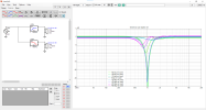
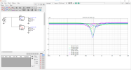
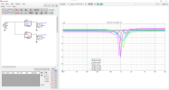
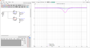
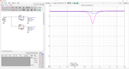
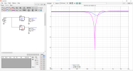
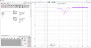
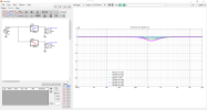
Here different wavelength c-c spacing using two ideal transducers and ideal LR4 xo showing the listed important vertical off-axis angles. Listening axis is always exactly midway between the two sources in these examples so always flat. The other lines show what the response is toward the other important vertical angles. Obviously 1/4wl spacing gives most similar response to all directions, but since it's usually physically impossible ~0.75wl is about best we can do unless it is a coaxial/MEH.
0.25wl.png0.75wl.png1wl.png1.25wl.png1.5wl.png2wl.png

On a quick look even the huge 1.5wl spacing looks just fine among the possible options, which is great relief for speaker designer because it means in some projects waveguide can fit big roundovers comfortably. If one wants to optimize some particular angle, then look closer for some particular c-c. The big c-c make CTA2034 DI and ERDI graphs look better so increases also the preference score sometimes used in this forum. What is better choise then clearly depends a lot of room acoustics, listening distance and height, how fixed the listening position, whether it's background or critical listening and so on.

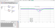
edit. oops, the above are missing +20deg angle, when one is standing ~2m away from speakers. So here another set just with 10 and 20deg off-axis, which represent various typical direct sound vertical listening angles.
0.75wl-standing.png1wl-standing.png1.25wl-standing.png1.5wl-standing.png2wl-standing.png

I'm reading from the graphs that regardless of c-c one should elevate the system to ear height to avoid dip around crossover. In general, dips are quite hard to perceive though, so personally I look the DI curves and don't mind about these particular angles but the average. My system has 1.2wl spacing and it is not obvious there is a dip around crossover when moving around the room, sitting standing and so on. If I get closer to speakers and search for it specifically, it's audible.

My understanding is that Marcel's software is intended for the DIY community and I'm not a DIYer. But I'm not convinced there is significant improvement to be made over the Oblate Spheroid profile, assuming constant directivity with minimal disturbance of the wavefront is the priority.
The whole thing started from OS profile and the fact that it's infinite and doesn't provide termination to baffle / freestanding, which easily leads to abrupt curvature change and diffraction. Marcel came up with math equation that is easy to tune so that computer simulation can be used to find good mouth termination for OS throat. See his papers on the at-horns.eu frontpage, first paper starts explaining this. If you start playing with the ATH profiles and simulating this stuff it's soon apparent all that matters is the curve, not the name of the curve, so in the end nothing else matters than the results. After all, it costs about the same to manufacture better or worse profile waveguide so why not try to squeeze best out of it. Traditionally it was very hard if not impossible to come up with good waveguide and difficult to manufacture it, now both are relatively trivial tasks.

I have not been favorably impressed with 3D printed horns thus far, but am waiting on a quote from a company who uses a technique that's significantly more advanced than desktop printing.
Yeah desktop printing is the easiest and cheapest way to get hold into this stuff, available for anyone anywhere in the world. One could do mold for casting or manufacture the device from wood in a lathe, CNC or anything, build it just like any other device is built.

Bottom line is that anything is possible today, within limits of physics of course :) So, the main problem with speakers is not the devices but the plan, to understand which kind of device aligns with requirements of the project. The devices, like drivers and waveguides are kind of irrelevant, as long as there is a plan there is likely the most suitable device available.

Phew, sorry for very long post and that I included the examples making it more general response than just a reply to yours.

In retrospect I was triggered a bit about the posts on this thread in general and I kind of described here how I see this stuff and that I'd gladly use freestanding waveguide with roundover and not think this c-c thing as a bad trade-off. Performance from mabat waveguides are so good I have no lust for anything else, I just roll my own as I see fit. Could do it for a dome tweeter if I wanted to use one. This is not attempt to push this stuff to anyone, just one perspective to things that was missing from the thread. So, if anyone hears a bad sounding horn system, it might not be fault of the horn but multiple things, while could be the horn as well. If it's the horn, just make a better one, it's trivial ;)

ps. I shouldn't do posts like this, takes a lot of energy and perhaps not very useful to anyone. :D
 
Last edited:
I used an angle- and curvature-matched section of an Euler spiral as the termination in my OS waveguide design. The axial ripple is not completely absent, but is pretty minor at about 2dB pk-pk. In contrast, a similarly sized OS waveguide with a 5 inch radius circular arc termination has an axial ripple of about 6dB pk-pk (according to simulation, at least).
I'm doing something similar. On a 12" diameter OSWG I'm getting a measured on-axis ripple of about 2 dB. I expect to have less on larger waveguides.

He said the following about a year ago:


But I bet he'd be willing to work out some kind of agreement if you wanted to offer compensation.
Reading Marcel's thread years ago confirmed to me that using something more sophisticated than a radius for the mouth termination was a good idea. I had something more complicated in mind.

I think a commercial loudspeaker is about to be launched, born of a collaboration project involving Earl and Marcel's work. Keep an eye on this link.

cheers
I didn't realize that, thanks!

When I look at the response curves of that Marcel thread on diyaudio, I don't grasp what the objective was (and whether the curves show it achieves with spectacular success).
My understanding is that one objective was to come up with a better mouth curvature than just grafting on a radius because the transition from the virtually straight-walled Oblate Spheroid curve to the radius could be made less abrupt and therefore less diffractive. I had been looking into a flower-petal-like mouth at one time to avoid a coherent on-axis mouth reflection but Marcel's idea of simply making the transition more gradual is far more elegant.

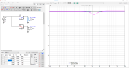
In 250cm tall room, 90cm listening height (sitting) at 2m listening distance, off-axis angles toward early specular reflections are roughly -40deg toward floor and 60deg toward ceiling. If listening distance is longer, these angles drop and are rouhgly -30deg and 50deg. If the person stood up he'd listen about at 20deg off-axis with the 2m listening distance and about 15deg when at 3m. +-10deg angles give some hint how much sound changes if head is not exactly at listening axis height. 10deg is about 35cm at 2m and about 50cm at 3m so various height people sitting at listening chair are likely much less than 10deg off-axis vertically.

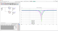
Here different wavelength c-c spacing using two ideal transducers and ideal LR4 xo showing the listed important vertical off-axis angles. Listening axis is always exactly midway between the two sources in these examples so always flat. The other lines show what the response is toward the other important vertical angles. Obviously 1/4wl spacing gives most similar response to all directions, but since it's usually physically impossible ~0.75wl is about best we can do unless it is a coaxial/MEH.
View attachment 389423View attachment 389424View attachment 389425View attachment 389422View attachment 389421View attachment 389420

On a quick look even the huge 1.5wl spacing looks just fine among the possible options, which is great relief for speaker designer because it means in some projects waveguide can fit big roundovers comfortably. If one wants to optimize some particular angle, then look closer for some particular c-c. The big c-c make CTA2034 DI and ERDI graphs look better so increases also the preference score sometimes used in this forum. What is better choise then clearly depends a lot of room acoustics, listening distance and height, how fixed the listening position, whether it's background or critical listening and so on.

edit. oops, the above are missing +20deg angle, when one is standing ~2m away from speakers. So here another set just with 10 and 20deg off-axis, which represent various typical direct sound vertical listening angles.
View attachment 389433View attachment 389432View attachment 389431View attachment 389430View attachment 389429

I'm reading from the graphs that regardless of c-c one should elevate the system to ear height to avoid dip around crossover. In general, dips are quite hard to perceive though, so personally I look the DI curves and don't mind about these particular angles but the average. My system has 1.2wl spacing and it is not obvious there is a dip around crossover when moving around the room, sitting standing and so on. If I get closer to speakers and search for it specifically, it's audible.

THANK YOU for going to so much trouble to graphically illustrate this for me! I do modeling in the vertical but use a different program. What you did gives me a very useful, somewhat different perspective. THANK YOU!!

The closest center-to-center spacing I've been comfortable with looks like about .77 wavelengths, still haven't decided on the final juggling of tradeoffs. (By using a 1.4" throat compression driver I can theoretically push the crossover down a bit lower than would be feasible with a 1" throat driver, at the cost of introducing compromises elsewhere, so it's a juggling of tradeoffs.)

Anyway obviously it's a good idea to get the ears on-axis (or close) in the vertical. On at least one floorstanding model I'll be using tilt-back to get listeners' ears closer to the correct vertical axis without having to make the enclosure too tall.
 
Last edited:
Back
Top Bottom