• WANTED: Happy members who like to discuss audio and other topics related to our interest. Desire to learn and share knowledge of science required. There are many reviews of audio hardware and expert members to help answer your questions. Click here to have your audio equipment measured for free!

E-MU 0204 in 2023, RMAA measurements, and some modifications

Rustin

Member
Joined
Mar 13, 2023
Messages
9
Likes
8
Location
Ukraine, Kharkiv
777.jpg

Well, I want to tell you a story about E-MU 0204 and how I tamed this wild beast from early 2000s in 2023. It all started back in 2018, I was building my amplifier on TPA3255EVM and I really needed a device that I could use for measuring as well as for normal daily tasks 24/7, and for connecting an electric guitar. I purchased the thing, but in the end, it didn't work properly. I searched a lot on various forums for a solution, but I could not find anything useful. The problem was in the first place nonworking drivers, which simply refused to find the device when installing them, but after some "dancing with tambourine", I did it, but there was a new problem - a click in the headphone output at the beginning and end of any sound. It was like the USB power just disappeared during the silence. In general I could not find anything to solve the problem and decided to sell the newly bought audio interface. It's been a long time since then, and you know what? I decided to try again. Why not, first of all it seems to me now that I gave up too quickly, in addition during this time I got new ideas to solve old problems, also there are fresh fixes on forums from different people. This time I decided to order this device from Poland because in my country it is "slightly" overpriced. The audio interface only cost me $45 including shipping, considering the fact that the device was in pretty much perfect condition think, it's a good deal. I ended up having exactly the same problems as in 2018, but this time it knew what to do. Drivers need to be manually installed in windows device manager. After that, the problem with clicks appeared again. I tried to connect an external power supply as advised on the forums, but in the it had absolutely no effect, also added a large amount of noise which was visible on the measurements. So I decided to leave this idea behind. The next solution to the clicking problem was software. One guy made a program which always plays silence. This way there is no beginning and no end for any sound, so no clicks. The program worked, but there were some details. For example, when computer went to sleep mode and out of it, seems that it's forcing audio interface to reboote, and any cycle of switching on/off device, makes so that fix stops working, and fix.exe process in task manager still sort of working, but clicks appear again, besides if I forget to restart fix.exe again manually then after time of work without it, device stops working at all, until I either reconnect USB plug or restart device in sound control panel of Windows. What came to my mind was to use the task scheduler. I had it to shut down fix.exe automatically when I went to sleep (to prevent a non-working fix from being suspended in processes). And when pc come out of sleep mode, the program automatically turned on. Ideally, the scheduler should be able to automatically reboot the device when it goes to and comes out of sleep mode, but I have not figured out how. It needs to be done due to the fact that if the computer goes to sleep and at the same time there will be playing any sound except silence from the fix, then after coming out of sleep mode the device will stuck and I have to manually reboot it and turn on the fix. But I am ready to put up with this problem. (If suddenly anyone knows how to set the reboot of a certain device in Windows 10 and link it to the sleep mode trigger in the task scheduler, let me know, I will be very glad). By the way, if you just decide to restart your computer, everything works perfectly, when you boot up windows, the fix program will automatically turn on. It is important to save folder with the fix before launching it for the first time, preferably somewhere in the folder in C:\Windows. I uploaded the fix and the working driver to google drive in case anyone need it. And so let's start the review, the measurements in RMAA:

Frequency response​


fr.png

2.jpg

Noise level​

noise.png

3.jpg

Dynamic range​

dynamics.png

4.jpg

THD + Noise (at -3 dB FS)​

thd.png

5.jpg

Intermodulation distortion​

imd.png

6.jpg

Stereo crosstalk​

cross.png

7.jpg

IMD (swept tones)​

imdswept.png

8.jpg

1.jpg


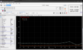
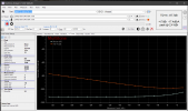
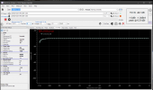
Output level is at 2V RMS. According to the results of measurements, we can see that there are some differences between the left and right channels, in the amplitude of low frequencies, let's look at the schematic and see what's what. (Don't pay attention to the small noise peak at 50 Hz, it comes and goes for indefinite reasons, maybe the reason is the very long cables I am using at the moment.)
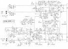
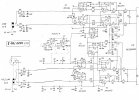
Original Scheme:
Original Scheme.jpg

Modified Scheme:
Scheme after upgrade.jpg

Basically, I'm not the first one who invented and realized this way of modification, so I won't describe it in details, I'll just show you schematic before and after the change and briefly describe the changes. If you are interested in the details, I would be happy to discuss it in comments. So, I removed unnecessary Op-Amp buffer cascade, a relay which switches line and microphone input, some resistors, transient capacitors, and some unnecessary components, which have no more use after the modification.​
fr.png

0.2.jpg
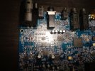
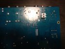
I also decided to try to turn an electret microphone input (this part is missing from the schematic) into a stereo line input, I removed the transition capacitor, removed the +5V track for phantom power and connected the 3.5 jack input to the XLR/TRS input with a jumper. But it turned out that the left and right inputs have a separate ground, so I had to abandon the idea and just make it as another left line input. Because combined XLR/TRS connector is grounding input until TRS connector is plugged in, it turns out, that 3.5 jack for line input can be used only when TRS is plugged in XLR/TRS, questionable modification I agree, but I don't need input for electret microphone anyway, at least I can connect two devices to one channel, let it be better this way. Of course, I could try to add identical input line by putting 2 resistors and diode and connect it to 3 pin, where the relay was, but I suspect that when you connect two inputs simultaneously to the op amp, a ground loop could form and it would work horribly, besides I don't have the smd resistors needed for this at hand, so I didn't do that.​

Here are some photos before and after:
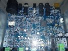
IMG_20230607_002407.jpg IMG_20230607_002631.jpg

IMG_20230608_170537.jpg IMG_20230608_170703.jpg

I haven't decided yet, but it might be worth replacing the output headphone op-amp with an LM4562, one guy did measurements and got less harmonic distortion under load, compared to the installed JRC2114.

Well, from my point of view E-MU 0204 very worthwhile thing, of course there are problems with the drivers, but if enough desire, they can be overcome, anyone who doubts whether to take this audio interface, I say - definitely yes!
 

Sokel

Master Contributor
Joined
Sep 8, 2021
Messages
6,120
Likes
6,195
I get much nicer results with the setting shown above,here's a couple (in REW too):


1Khz SINAD.PNG


1Khz SINAD


IMD.PNG


IMD

Multitone32.PNG


Multitone 32

Seems that it's ADC is much nicer than it's DAC,here's what i get measuring Khadas Tone (110db SINAD when measured by Amir:


KhadasTone1.jpg


What you see in unmodded,USB powered by PC (not laptop).
 
Last edited:

Sokel

Master Contributor
Joined
Sep 8, 2021
Messages
6,120
Likes
6,195
About the drivers and stuff.
I use 6.0.1.1 driver (2010) in windows 10 with absolutely no problem (as you can see in measurements).

Never had the ticking sound problem but since you do it might help to turn of the energy saving setting for the USB port it uses.
E-MU's are power hungry,better use a port that can deliver.

(externally powered gets even better numbers but the point is it's raw performance).
 

SSS

Senior Member
Joined
Jan 12, 2023
Messages
319
Likes
201
Location
Germany

Well, I want to tell you a story about E-MU 0204 and how I tamed this wild beast from early 2000s in 2023. It all started back in 2018, I was building my amplifier on TPA3255EVM and I really needed a device that I could use for measuring as well as for normal daily tasks 24/7, and for connecting an electric guitar. I purchased the thing, but in the end, it didn't work properly. I searched a lot on various forums for a solution, but I could not find anything useful. The problem was in the first place nonworking drivers, which simply refused to find the device when installing them, but after some "dancing with tambourine", I did it, but there was a new problem - a click in the headphone output at the beginning and end of any sound. It was like the USB power just disappeared during the silence. In general I could not find anything to solve the problem and decided to sell the newly bought audio interface. It's been a long time since then, and you know what? I decided to try again. Why not, first of all it seems to me now that I gave up too quickly, in addition during this time I got new ideas to solve old problems, also there are fresh fixes on forums from different people. This time I decided to order this device from Poland because in my country it is "slightly" overpriced. The audio interface only cost me $45 including shipping, considering the fact that the device was in pretty much perfect condition think, it's a good deal. I ended up having exactly the same problems as in 2018, but this time it knew what to do. Drivers need to be manually installed in windows device manager. After that, the problem with clicks appeared again. I tried to connect an external power supply as advised on the forums, but in the it had absolutely no effect, also added a large amount of noise which was visible on the measurements. So I decided to leave this idea behind. The next solution to the clicking problem was software. One guy made a program which always plays silence. This way there is no beginning and no end for any sound, so no clicks. The program worked, but there were some details. For example, when computer went to sleep mode and out of it, seems that it's forcing audio interface to reboote, and any cycle of switching on/off device, makes so that fix stops working, and fix.exe process in task manager still sort of working, but clicks appear again, besides if I forget to restart fix.exe again manually then after time of work without it, device stops working at all, until I either reconnect USB plug or restart device in sound control panel of Windows. What came to my mind was to use the task scheduler. I had it to shut down fix.exe automatically when I went to sleep (to prevent a non-working fix from being suspended in processes). And when pc come out of sleep mode, the program automatically turned on. Ideally, the scheduler should be able to automatically reboot the device when it goes to and comes out of sleep mode, but I have not figured out how. It needs to be done due to the fact that if the computer goes to sleep and at the same time there will be playing any sound except silence from the fix, then after coming out of sleep mode the device will stuck and I have to manually reboot it and turn on the fix. But I am ready to put up with this problem. (If suddenly anyone knows how to set the reboot of a certain device in Windows 10 and link it to the sleep mode trigger in the task scheduler, let me know, I will be very glad). By the way, if you just decide to restart your computer, everything works perfectly, when you boot up windows, the fix program will automatically turn on. It is important to save folder with the fix before launching it for the first time, preferably somewhere in the folder in C:\Windows. I uploaded the fix and the working driver to google drive in case anyone need it. And so let's start the review, the measurements in RMAA:

Frequency response​


Noise level​

Dynamic range​

THD + Noise (at -3 dB FS)​

Intermodulation distortion​

Stereo crosstalk​

IMD (swept tones)​


Output level is at 2V RMS. According to the results of measurements, we can see that there are some differences between the left and right channels, in the amplitude of low frequencies, let's look at the schematic and see what's what. (Don't pay attention to the small noise peak at 50 Hz, it comes and goes for indefinite reasons, maybe the reason is the very long cables I am using at the moment.)
Original Scheme:
View attachment 291007

Modified Scheme:
View attachment 291008

Basically, I'm not the first one who invented and realized this way of modification, so I won't describe it in details, I'll just show you schematic before and after the change and briefly describe the changes. If you are interested in the details, I would be happy to discuss it in comments. So, I removed unnecessary Op-Amp buffer cascade, a relay which switches line and microphone input, some resistors, transient capacitors, and some unnecessary components, which have no more use after the modification.​
I also decided to try to turn an electret microphone input (this part is missing from the schematic) into a stereo line input, I removed the transition capacitor, removed the +5V track for phantom power and connected the 3.5 jack input to the XLR/TRS input with a jumper. But it turned out that the left and right inputs have a separate ground, so I had to abandon the idea and just make it as another left line input. Because combined XLR/TRS connector is grounding input until TRS connector is plugged in, it turns out, that 3.5 jack for line input can be used only when TRS is plugged in XLR/TRS, questionable modification I agree, but I don't need input for electret microphone anyway, at least I can connect two devices to one channel, let it be better this way. Of course, I could try to add identical input line by putting 2 resistors and diode and connect it to 3 pin, where the relay was, but I suspect that when you connect two inputs simultaneously to the op amp, a ground loop could form and it would work horribly, besides I don't have the smd resistors needed for this at hand, so I didn't do that.​

Here are some photos before and after:
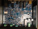
View attachment 291012 View attachment 291013

View attachment 291001 View attachment 291002

I haven't decided yet, but it might be worth replacing the output headphone op-amp with an LM4562, one guy did measurements and got less harmonic distortion under load, compared to the installed JRC2114.

Well, from my point of view E-MU 0204 very worthwhile thing, of course there are problems with the drivers, but if enough desire, they can be overcome, anyone who doubts whether to take this audio interface, I say - definitely yes!
Thank you for the report. I use a non-modified E-MU Tracker with external power supply for measurements. With Win-10-Pro there is good performance when I use the ASIO4ALL driver. But I use only the line level input calibrated to 0 dB (0.775 V) voltage for 0 dB FS. Can measure to almost 100 kHz. There is an elevated noise level compared to 10 kHz.
 
OP
Rustin

Rustin

Member
Joined
Mar 13, 2023
Messages
9
Likes
8
Location
Ukraine, Kharkiv
I get much nicer results with the setting shown above,here's a couple (in REW too):


View attachment 291083

1Khz SINAD


View attachment 291084


IMD

View attachment 291087

Multitone 32

Seems that it's ADC is much nicer than it's DAC,here's what i get measuring Khadas Tone (110db SINAD when measured by Amir:


View attachment 291085


What you see in unmodded,USB powered by PC (not laptop).
Sorry, but but i dont think you are right, the DAC in it is way better than its own ADC can measure. Line output has about 117dB of dynamic range while the input has 113dB. Regarding your measurement results I can say that I noticed some different interpretation of measurements using different kind of measurement software, so I'm sure all E-MU devices +- within small errors have identical readings, the rest depends on the software you use for measurements. About the drivers, I use the same version as you, and it works fine, but there are some problems with asio, but restarting the program that uses it usually helps solve the problem, besides I use only RMAA program for measurements, and it works fine even without asio.

As for the click at the end and beginning of sound playback, the problem appears exactly on the headphone output, on the line such a problem is not noticed, or it is on the verge of recognizing it by ear. All these settings of ports I have already tried, as well as tried to disable everything unnecessary through the bios + repeated the same on several other PCs, but alas, the problem remains. The only thing is that on my laptop, e-mu is not disconnected when going to sleep and coming out of it, so there is no problem with the need to run the fix or stop playing any audio signal when going to sleep. In general, as I noticed different PCs turn off the USB power at different times at the moment of entering sleep mode. If USB power is turned off first and then the computer goes to sleep, there is a problem with the fix turning off and the e-mu device lagging/freezing after sleep mode. But if PC goes to sleep first and then turns off the USB ports, this problem does not exist at all and there is no need to run e-mu fix again.

As for power hungry, I can not say anything of the kind, I connected my E-MU to a laboratory power supply and got values of about 450mA - 470mA, before the modification, this is quite acceptable load, given that the usb port outputs a maximum of 500mA. After modification the device began to consume 410 - 430mA, due to the fact that I removed the relay and opamp that consume a little energy.
 
Last edited:

Sokel

Master Contributor
Joined
Sep 8, 2021
Messages
6,120
Likes
6,195
OP
Rustin

Rustin

Member
Joined
Mar 13, 2023
Messages
9
Likes
8
Location
Ukraine, Kharkiv
Thank you for the report. I use a non-modified E-MU Tracker with external power supply for measurements. With Win-10-Pro there is good performance when I use the ASIO4ALL driver. But I use only the line level input calibrated to 0 dB (0.775 V) voltage for 0 dB FS. Can measure to almost 100 kHz. There is an elevated noise level compared to 10 kHz.
Yes, of course, at higher frequencies, the noise level is higher, although I don’t quite understand why it is generally necessary to measure anything in an audio signal above 20 kHz
 
OP
Rustin

Rustin

Member
Joined
Mar 13, 2023
Messages
9
Likes
8
Location
Ukraine, Kharkiv
AKM's PDF gives 100db THD+N for AK4396 DAC it uses (often call "miracle DAC" back in it's days)


On the other hand it's AK5385 ADC measures like this:

View attachment 291123

So clearly better.
Yes, perhaps based on the datasheet data, you are right, but I can’t say the same about real solutions in devices, there are several measurements on the Internet, where e-mu 0204 was connected to a higher-class ADC, and the measurements of line output values turned out to be better than when e-mu 0204 measuring itself
 
OP
Rustin

Rustin

Member
Joined
Mar 13, 2023
Messages
9
Likes
8
Location
Ukraine, Kharkiv
AKM's PDF gives 100db THD+N for AK4396 DAC it uses (often call "miracle DAC" back in it's days)


On the other hand it's AK5385 ADC measures like this:

View attachment 291123

So clearly better.
Although it is possible that the level of harmonics will be lower in the ADC, but definitely not the noise level.
 

Sokel

Master Contributor
Joined
Sep 8, 2021
Messages
6,120
Likes
6,195
Although it is possible that the level of harmonics will be lower in the ADC, but definitely not the noise level.
DAC's S/N is 120db and ADC's S/N is 114db so thats true,but you can't avoid that harmonics for sure,specially the 3rd who spoils it big time,it would be in the realm of 108db SINAD without it.
 
OP
Rustin

Rustin

Member
Joined
Mar 13, 2023
Messages
9
Likes
8
Location
Ukraine, Kharkiv
DAC's S/N is 120db and ADC's S/N is 114db so thats true,but you can't avoid that harmonics for sure,specially the 3rd who spoils it big time,it would be in the realm of 108db SINAD without it.
Totally agree. But the question is which is better, less noise but more harmonics or less harmonics but more noise, depends on the purpose of use.
 

SSS

Senior Member
Joined
Jan 12, 2023
Messages
319
Likes
201
Location
Germany
Yes, of course, at higher frequencies, the noise level is higher, although I don’t quite understand why it is generally necessary to measure anything in an audio signal above 20 kHz
True, for audio only up to 20 kHz measurement is sufficient. Up to 100 kHz is good to measure amplifiers. And I found that some digital audio equipment has steady frequencies around 40 kHz, maybe from switched power supply. To measure class-D amps it should go to the MHz ranges to see switching noise.
 
OP
Rustin

Rustin

Member
Joined
Mar 13, 2023
Messages
9
Likes
8
Location
Ukraine, Kharkiv
True, for audio only up to 20 kHz measurement is sufficient. Up to 100 kHz is good to measure amplifiers. And I found that some digital audio equipment has steady frequencies around 40 kHz, maybe from switched power supply. To measure class-D amps it should go to the MHz ranges to see switching noise.
I think it would be more appropriate to measure switching noise of class-D amps with a good oscilloscope, but if your ADC allows you to do such measurements, then why not. I would like to take a look!
 

SSS

Senior Member
Joined
Jan 12, 2023
Messages
319
Likes
201
Location
Germany
I think it would be more appropriate to measure switching noise of class-D amps with a good oscilloscope, but if your ADC allows you to do such measurements, then why not. I would like to take a look!
My audio interface of course cannot measure MHz signals. There I use a digital oscilloscope with FFT capability. But I don't like class-D amps and I have no one, thus no measurements available.
 

Sokel

Master Contributor
Joined
Sep 8, 2021
Messages
6,120
Likes
6,195
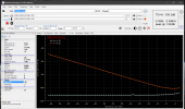
I thought it would be nice to have a complete set of measurements since that's the thread is all about so I'll add some more:

THD+N vs Level.PNG

THD+N vs Level (plus Noise vs Level)


THD+N vs Frequency.PNG

THD+N vs Frequency (plus Noise vs Frequency)


IMD vs Level.PNG

IMD vs Level (plus IMD vs Noise)


Linearity.PNG

Linearity


(Not bad for a 15 years old,100 euro interface I think)
 

Sokel

Master Contributor
Joined
Sep 8, 2021
Messages
6,120
Likes
6,195
If we talk about mods,I removed the crappy pot,put a couple of resistors in it's place and H2 went 12db down.
(you can compare it with the gazillion measurements I have uploaded here.)


-12db.PNG


It doesn't impact overall SINAD as the H3 stays proudly at -105 (-107-108db in it's good days,depending the temp) but still...
 
OP
Rustin

Rustin

Member
Joined
Mar 13, 2023
Messages
9
Likes
8
Location
Ukraine, Kharkiv
If we talk about mods,I removed the crappy pot,put a couple of resistors in it's place and H2 went 12db down.
(you can compare it with the gazillion measurements I have uploaded here.)


View attachment 296082

It doesn't impact overall SINAD as the H3 stays proudly at -105 (-107-108db in it's good days,depending the temp) but still...
Very interesting, could you please be more specific, what exactly did you change in the scheme?
 

Sokel

Master Contributor
Joined
Sep 8, 2021
Messages
6,120
Likes
6,195
Very interesting, could you please be more specific, what exactly did you change in the scheme?
Just unsoldered the gain pot,measured the resistances between the legs and replaced it with 2 resistors,the old DIY way.
First chance when I gather some things in mouser I'll get some nice Alps pots small ones to fit them.
 

AnalogSteph

Major Contributor
Joined
Nov 6, 2018
Messages
3,393
Likes
3,341
Location
.de
If we talk about mods,I removed the crappy pot,put a couple of resistors in it's place and H2 went 12db down.
How do we explain this? My first guess would be input impedance distortion as a result of poor contact at the wiper... but this is a balanced input using two halves of a stereo opamp, so I'd expect pretty good matching and hence cancellation of even-order distortion. Weird.
 

Sokel

Master Contributor
Joined
Sep 8, 2021
Messages
6,120
Likes
6,195
How do we explain this? My first guess would be input impedance distortion as a result of poor contact at the wiper... but this is a balanced input using two halves of a stereo opamp, so I'd expect pretty good matching and hence cancellation of even-order distortion. Weird.
E-Mu's pots unlike it's rest of materials where always it's weak spot.
Imagine after 13 years!
Your guess is as good as mine,I only did it cause I remembered where H2 was when it was fairly new and a friend of mine measured it back then.

Thing is I have seen crazy stuff messing with it,once (just once) I got a loopback SINAD of 107db out of the blue when H3 decided to go to -110db when warm from soldering.
Temp is a thing for it,whether it gets warm by itself or extreme room fluctuations.Best when normal temp after some time using it.

Edit:Measurement is a loopback,unbalanced L output (E-MU doen't have balanced outputs) > balanced L input (shorted cold and ground at the output).
I just let Multitone to play both channels for convenience so I swap them on the fly.
 
Last edited:
Top Bottom