dougi
Addicted to Fun and Learning
INTRODUCTION AND DESCRIPTION
Hi all. I'm posting measurements of the Dynavox TPR-2 line/phono tube output preamp. Sorry US members, only available in 230V AC.
Pics, description and specs can be found on the Audiophonics page. It's a solid state phono preamp with a 12au7 triode output, used direct for the line input. With a seperate power supply unit to generate the various AC voltages, which are then rectified within the main unit.
A circuit seems to be floating around for it on ye olde flickr. As can be seen from the circuit:
The guts of mine:

MEASUREMENT APPROACH
I used my RME ADI-2 PRO FS R for measurements, driven by @pkane 's multitone software. It's excellent in this application, especially with the ability to apply an inverse RIAA curve to the generator to test RIAA accuracy. To limit time, I generated using the RME +4dBu range (1.23V) and +19dBu (6.9V) on the ADC (input) side. Yes, this means no CD level tests but you will soon see that is not too important.
LINE STAGE
At max volume, with the pot preceding the tube, and 1.23V in, this is the result below. Level out is -7.4dBFS wrt 6.9V = 2.94V, so ~7.6dB gain. Lots of distortion with this drive level, but very quiet with just the tube stage. Note, given the likely high output impedance, this will be higher into loads with a higher input impedance that the RME's 9kohm. I confirmed this by repeating a measurement into my NAD C3050LE, with an impedance of 28kohm (set to unity gain). Gain of the unit was around 3dB higher. With the two measurements, you can then solve the voltage divider simultaneous equations to estimate an output impedance of the TPR-2 of ~7150ohms.

Backing off the input a bit to 0.5V, still wide open improves things a bit. If you want to use a 2V source, you will need to keep the volume low to keep distortion reasonable.

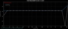
A THD+N vs level sweep shows the gradual rise in THD:

For brevity, I wont show the very flat THD vs frequency curve, but here is the very good line input crosstalk:

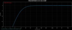
Frequency response shows some drop-off at the lower end. Note this was 0.5dB better at 20 Hz into the higher impedance NAD:

This is probably enough on the line input, but here's CCIR at 0.5V in, volume set to unity gain. It again illustrates the flat distortion performance of something with no feedback:

PHONO STAGE
I wont show all 1kHz plots as they are affected by grounding, but at full volume, mm gain was 39.4dB, mc was 53.3dB. Which is strange, given the circuit show give 20dB higher for mc over mm. NOTE: input was 5mV, not 0.5mV!

RIAA response shows within +-0.5dB in the audio-band, with rolloff below and lift above (again title error was 5mV in):

OVERLOAD: reducing volume to "half" to be able to focus on the phono stage, overload for mm at 1kHz is ~69mV: Ignore +N given grounding issues.

For mc, it was about 12mV in, but a very soft clip. Again focus on THD rather than THD+N due to grounding. I hope to measure overload at other frequencies as well. Sorry for a different scale to the previous plot (dBV out rather than dBFS at the output).

Crosstalk with phono stage, again pretty good:

What about noise? After reading the LT1028 datasheet, it made for interesting reading about noise vs source impedance. Hence I measured noise with a cartridge attached, AT VM540ML for mm and AT OC9XEN for mc. Yes, I could have used resistors but attaching a cart was easier and perhaps more representative of use. I also obtained some (expensive) LT1028s and tried them (after soldering in DIL sockets):
Given the specs state a mm SNR of 68dB for mm and 70dB for mc, this is perhaps A weighted and for the LT1028 as was in the schematic. Close to what I measured.
CONCLUSIONS
It seems a competent design, within the constraints of the triode output! I have reduced the mm input capacitance to ~100pF and may try other opamp types (perhaps NE4434A-grade in an attempt to get a balanced noise performance between mm and mc. I will also investigate the mc gain and perhaps lift it up a bit by changing the first stage resistor switched in if the value is not as expected.
For driving a power amp the high output impedance may not be an issue, but may use is as a phono pre into the NAD C3050LE. Lucky it's input impedance is reasonable.
Hi all. I'm posting measurements of the Dynavox TPR-2 line/phono tube output preamp. Sorry US members, only available in 230V AC.
Pics, description and specs can be found on the Audiophonics page. It's a solid state phono preamp with a 12au7 triode output, used direct for the line input. With a seperate power supply unit to generate the various AC voltages, which are then rectified within the main unit.
A circuit seems to be floating around for it on ye olde flickr. As can be seen from the circuit:
- two stage active RIAA for phono, with supposedly LT1028 in the first stage, NE5534 in the second (RIAA) stage.
- rather high mm capacitance loading with 377pF total
- single 12au7 dual triode with no feedback, so high distortion and output impedance likely
- rectification inside the main box.
The guts of mine:
MEASUREMENT APPROACH
I used my RME ADI-2 PRO FS R for measurements, driven by @pkane 's multitone software. It's excellent in this application, especially with the ability to apply an inverse RIAA curve to the generator to test RIAA accuracy. To limit time, I generated using the RME +4dBu range (1.23V) and +19dBu (6.9V) on the ADC (input) side. Yes, this means no CD level tests but you will soon see that is not too important.
LINE STAGE
At max volume, with the pot preceding the tube, and 1.23V in, this is the result below. Level out is -7.4dBFS wrt 6.9V = 2.94V, so ~7.6dB gain. Lots of distortion with this drive level, but very quiet with just the tube stage. Note, given the likely high output impedance, this will be higher into loads with a higher input impedance that the RME's 9kohm. I confirmed this by repeating a measurement into my NAD C3050LE, with an impedance of 28kohm (set to unity gain). Gain of the unit was around 3dB higher. With the two measurements, you can then solve the voltage divider simultaneous equations to estimate an output impedance of the TPR-2 of ~7150ohms.
Backing off the input a bit to 0.5V, still wide open improves things a bit. If you want to use a 2V source, you will need to keep the volume low to keep distortion reasonable.
A THD+N vs level sweep shows the gradual rise in THD:
For brevity, I wont show the very flat THD vs frequency curve, but here is the very good line input crosstalk:
Frequency response shows some drop-off at the lower end. Note this was 0.5dB better at 20 Hz into the higher impedance NAD:
This is probably enough on the line input, but here's CCIR at 0.5V in, volume set to unity gain. It again illustrates the flat distortion performance of something with no feedback:
PHONO STAGE
I wont show all 1kHz plots as they are affected by grounding, but at full volume, mm gain was 39.4dB, mc was 53.3dB. Which is strange, given the circuit show give 20dB higher for mc over mm. NOTE: input was 5mV, not 0.5mV!
RIAA response shows within +-0.5dB in the audio-band, with rolloff below and lift above (again title error was 5mV in):
OVERLOAD: reducing volume to "half" to be able to focus on the phono stage, overload for mm at 1kHz is ~69mV: Ignore +N given grounding issues.
For mc, it was about 12mV in, but a very soft clip. Again focus on THD rather than THD+N due to grounding. I hope to measure overload at other frequencies as well. Sorry for a different scale to the previous plot (dBV out rather than dBFS at the output).
Crosstalk with phono stage, again pretty good:
What about noise? After reading the LT1028 datasheet, it made for interesting reading about noise vs source impedance. Hence I measured noise with a cartridge attached, AT VM540ML for mm and AT OC9XEN for mc. Yes, I could have used resistors but attaching a cart was easier and perhaps more representative of use. I also obtained some (expensive) LT1028s and tried them (after soldering in DIL sockets):
- mm, NE5534, SNR 75dB, 78dBA
- mm, LT1028, SNR 65 dB, 67 dBA
- mc, NE5534, SNR 58dB, 64 dBA
- mc, LT1028, SNR 64 dB, 71 dBA
Given the specs state a mm SNR of 68dB for mm and 70dB for mc, this is perhaps A weighted and for the LT1028 as was in the schematic. Close to what I measured.
CONCLUSIONS
It seems a competent design, within the constraints of the triode output! I have reduced the mm input capacitance to ~100pF and may try other opamp types (perhaps NE4434A-grade in an attempt to get a balanced noise performance between mm and mc. I will also investigate the mc gain and perhaps lift it up a bit by changing the first stage resistor switched in if the value is not as expected.
For driving a power amp the high output impedance may not be an issue, but may use is as a phono pre into the NAD C3050LE. Lucky it's input impedance is reasonable.
Attachments
Last edited: