• WANTED: Happy members who like to discuss audio and other topics related to our interest. Desire to learn and share knowledge of science required. There are many reviews of audio hardware and expert members to help answer your questions. Click here to have your audio equipment measured for free!

DIY Purifi Amp builds

I well understand... and if you noticed I was replying to a very helpful post about the NC400 IN THIS THREAD... (which clearly didn't stay on topic over it's 136 pages). But it's HERE, and that's why I asked for clarification. :)

Thank you for your other input. I've gotten mixed input from other sources and queries. Always the most frustrating aspect of trying a new path. However, yours and a few others are clearly showing to be in the category of Best Practice. I appreciate your vote for that!

Cheers.
Yes. I understand. Sorry there was not more help for you in a directly applicable thread. I have done several NC400s, mono and stereo, in Ghent cases. ;)

Do you feel confident to proceed with building yours now?
 
Yes. I understand. Sorry there was not more help for you in a directly applicable thread. I have done several NC400s, mono and stereo, in Ghent cases. ;)

Do you feel confident to proceed with building yours now?
There is a YouTube video on how to build out the NC400 amps from kits:


It's a very straightforward project. Best of luck.
 
Yes. I understand. Sorry there was not more help for you in a directly applicable thread. I have done several NC400s, mono and stereo, in Ghent cases. ;)

Do you feel confident to proceed with building yours now?
Thanks. I cast a lot of lines and have received some good feedback from a few folk since yesterday. If I were using the standard Hypex Kits, it wouldn't be a problem, but these Ghent 2- and 3-channel Chassis are more... shall we say, intermediate level? ;) ...with wiring that doesn't fit right or else is only terminated on one side. :p

I've got terminations and contacts coming from DigiKey to fix that, I've got good instructions on connecting to the Female XLR Chassis Mounts, and as of just a few minutes ago, some further guidance regarding other grounding of the modules.

All told, I'm in a good place, I think. I will say, though, I am SUPER GLAD I didn't try to order a Chassis from DIY Audio Store and go at it from scratch!!! :D

There is a YouTube video on how to build out the NC400 amps from kits:
I watched that too, in hopes of finding the answers, but for their kit, Hypex supplies all the right parts! ;) So in that regard, this wasn't as helpful as a guide on putting it all together. ;)

Cheers, Gentlemen.
folded-hands_1f64f.png
 
There is a YouTube video on how to build out the NC400 amps from kits:


It's a very straightforward project. Best of luck.

It is a pretty straightforward project although the new Nilai instructions and videos are incredibly better.

The NRD video is more like a superlative-laden infomercial than helpful build advice. Fortunately, Hypex fixed most of these shortcomings by providing terminated cabling and so the video is quite irrelevant.:oops:
 
Last edited:
For reference, here is the schematic of buffer in the Hypex NC500 eval board.
View attachment 88912

Here is the Purifi eval board buffer. Notice the missing components in the Hypex eval board?
View attachment 88913
It looks like the Audiophonics buffer board lacks EMI filtering and GBW limiting too? Unless they've put the required caps on the bottom layer which seems unlikely:
purifi_bypass_gain_0.jpg


That "blog post" is from june 2020 though; maybe they've added it since?
 
I'm surprised no-one has made a right-angle buffer board. Something like this:
purifi-buffer-2023-03-25-front.jpg
Should be space efficient, right? (Unless something interferes with the 1ET400 board...) Note I'm just fooling around here; I don't even have an 1ET400, and I'm not sure I will buy any. I am also not a professional circuit/pcb designer! If someone is interested in trying it out though despite it being untested and designed by an amateur, I can publish the design (KiCAD).

Schematic:
purifi-buffer-sch-20230325.png
It's almost exactly the EVAL1 buffer, just with an additional 1 nF cap for improved EMI filtering (can be left unmounted if one so wishes). Oh and with three gain options: unity, fixed (14.6 dB, same as EVAL1), and variable (3.5-9.5 dB as drawn, but e.g. 3.9-14.6 dB is possible by changing R17b1 to 1k5), selected by jumpers and trimpot. The PCB layout is a bit different too so no guarantees about sound quality (or even stability!). Resistors and SMD caps are 0805 for easy hand soldering.
 
I'm surprised no-one has made a right-angle buffer board. Something like this:
View attachment 274578
Should be space efficient, right? (Unless something interferes with the 1ET400 board...) Note I'm just fooling around here; I don't even have an 1ET400, and I'm not sure I will buy any. I am also not a professional circuit/pcb designer! If someone is interested in trying it out though despite it being untested and designed by an amateur, I can publish the design (KiCAD).

Schematic:
View attachment 274584
It's almost exactly the EVAL1 buffer, just with an additional 1 nF cap for improved EMI filtering (can be left unmounted if one so wishes). Oh and with three gain options: unity, fixed (14.6 dB, same as EVAL1), and variable (3.5-9.5 dB as drawn, but e.g. 3.9-14.6 dB is possible by changing R17b1 to 1k5), selected by jumpers and trimpot. The PCB layout is a bit different too so no guarantees about sound quality (or even stability!). Resistors and SMD caps are 0805 for easy hand soldering.

Hello, this is exactly what I was looking for! an Adjustable Gain to fine-tune my Anthem MRX which is 3.2Vrms at the RCA output. From what is commonly done with Purifi modules, you could add Voltage regulators.

You can surely take inspiration from a Buffer distributed for free by improving it available here: https://www.diyaudio.com/community/threads/universal-pcb-for-purifi-1et400a-amps.379211/post-6855612

I would be happy to "test" / "listen" to your final Buffer V1 once it matches my Anthem MRX as closely as possible.

Good continuation, do not hesitate to contact me if you have any questions.
 
Hi DonVinc3nzo. Thank you for your comment!

I will not add voltage regulators: I wanted to make the simplest possible "breakout board" for the 1ET400A, and I think I've done that, pretty much. I.e. soldered wire connections - connectors are bulky and expensive - and no superflous functions. Tom (of Neurochrome) couldn't measure any advantage of extra voltage regulation when using the Hypex SMPS1200 PSU, and if he cannot even measure it, then surely there is no audible benefit! (It's reasonable for Purifi to include voltage regulation on the EVAL boards though since they need to ensure 100 % sound quality regardless of PSU used for evaluation.)

What is needed is a buffer: to get usable amplification, high input impedance, and for EMI filtering, I guess. So I included that and the I/O connections for the PSU (/AMPON, /FATAL), and nothing else. (Again, it's reasonable for purifi to include a buffer bypass for evaluation purposes - I chose buffered unity gain instead.)

I've looked at all the 3rd party buffers I could find good pictures of online, including the one you link to, and what strikes me is that none, with the exception of the Neurochrome buffer, seems to me to add anything useful - except perhaps low cost, which is of course perfectly fine by itself. (The Neurochrome buffer has what looks like excellent EMI filtering, even including some inductors, and the DC servo which might be useful.) My design was intended to be simple, small, and low cost, hopefully without giving up any sound quality. It needs testing though; I really don't know how it performs!

Interestingly, no 3rd party buffers I've seen seems to have picked up on the excellent PCB layout of the EVAL1 buffers. I traced the tracks using the schematic and component layout published in the EVAL1 documentation, and they've done a professional job of routing the signal as a differential pair. The 3rd party buffers I've seen either have pretty horrible pcb layout with no regards for signal integrity at all (like the one you linked), or they fall into the "symmetrical, mirrored layout" trap which may look good, but in the words of Putzey himself "are exactly the wrong way to do it" (see Putzey: The G Word, or How to Get Your Audio off the Ground, pp 11). The Neurochrome board falls into the latter category.

To be fair, I don't think treating the signal as a true differential pair matters one iota at audio frequencies - but it could have an effect on EMI rejection, perhaps. It's probably a non-issue; I'm not saying there's anything wrong with the Neurochrome buffer! But it felt nice to see how well it's done on the EVAL1 board - and I was at least inspired by this while laying out my buffer, although the EVAL1 is still better in this regard.

(Sorry for the wall of text; it's an interesting subject. :))
 
Those who are curious about a subjective review of the Neurochrome 1ET400A / Hypex NC500 Input Buffer versus the Purifi EVAL1 should have a look at this review in Positive Feedback: https://positive-feedback.com/audio-discourse/neurochrome-purifi-1et400a-hypex-nc500-input-buffer/

The Neurochrome buffer has what looks like excellent EMI filtering, even including some inductors, and the DC servo which might be useful.
You're correct about the EMI filter. It does not have a DC servo, though.

The 3rd party buffers I've seen either have pretty horrible pcb layout with no regards for signal integrity at all (like the one you linked), or they fall into the "symmetrical, mirrored layout" trap which may look good, but in the words of Putzey himself "are exactly the wrong way to do it" (see Putzey: The G Word, or How to Get Your Audio off the Ground, pp 11). The Neurochrome board falls into the latter category.
I agree that most layouts are awful. I fail to see how the Neurochrome 1ET400A Input Buffer falls into the category of "symmetrical, mirrored layout trap" though. I follow Bruno's approach and keep the differential signal running as a differential pair with a small loop area wherever possible as well. I get stellar measured performance as result.

Tom
 
If you already have the SMPS1200A400 power supply and two Purifi 1ET400A amp modules, all you need is this:

2x Purifi 1ET400A / Hypex NC500 Input Buffer
1x SMPS Splitter

You'll also need two wiring harnesses to connect from the SMPS Splitter to each of the two buffers and a 10-pin ribbon cable that connects the SMPS and Buffers. I can help you with those. Just toss me an email. I should probably build some up so I can offer the whole shebang as a kit.

Finally you'll need some female XLR connectors for the input and some speaker output terminals. I offer some decent binding posts and also highly recommend the speakON connectors by Neutrik. You can buy those (and the XLR connectors) through Mouser (www.mouser.com).

If you don't have a chassis, the one I offer is a very nice option: https://neurochrome.com/collections/connectors-parts/products/purifi-chassis

Tom
 
You're correct about the EMI filter. It does not have a DC servo, though.
I meant the part with the LME49724. It's meant to keep the differential signals symmetric around 0V, right? (I.e. the average to 0V. Perhaps it's incorrect to call it a DC servo; I'm not really familiar with the term.)

I agree that most layouts are awful. I fail to see how the Neurochrome 1ET400A Input Buffer falls into the category of "symmetrical, mirrored layout trap" though. I follow Bruno's approach and keep the differential signal running as a differential pair with a small loop area wherever possible as well. I get stellar measured performance as result.
Have you traced the layout of the EVAL1 board? I would say the difference between that board and yours is apparent, with your board using a mirrored layout (one "side" for the negative, one for the positive) while the EVAL1 uses a "proper" differential pair layout. Compare the loop areas:

Neurochrome v2:
Neurochrome-buffer-board-v2-pcb.png


EVAL1:
EVAL1.png


Again, this would matter if this was an oscilloscope frontend, or a USB data pair. Not so much for audio frequencies! I have no reason to doubt your measurements. I just thought it was neat to see how well (this part of) the EVAL1 was designed, and I though it was interesting that none of the third party buffers seem to have picked up on that before. That's all.
 
Last edited:
There's quite a bit of loop area by the opamp in Bruno's layout as well. But, yeah... His layout is tighter than mine. I'm fine with that. :) Had I not allowed for gain switching by jumpers - a feature requested by my customers - I could have made the layout much tighter.

The proper term for the LME49724 is a differential amp. Or "fully differential" if you want to use TI's terminology. Differential in. Differential out.

Tom
 
True that! The input impedance of the Purifi modules is quite low.

Tom
Maybe a chance for you as a DIY supplier. Why not to design an input buffer with gain = 1 and high input impedance, based on JFET/CMOS input opamp like OPA2156?

 
Last edited:
I have Purifi EVAL2 kit on the way …. :).

Unfortunately, the 1st round has not been successful. With all PSU voltages within specs, the amp refused to make switching, the output stage does not oscillate. I have sent the return request to https://www.soundimports.eu/en/ and would like to get a replacement unit.
 

Attachments

  • EVAL2_testbench_small.jpg
    EVAL2_testbench_small.jpg
    237.5 KB · Views: 110
  • EVAL2_J10_voltages.png
    EVAL2_J10_voltages.png
    132.5 KB · Views: 107
  • EVAL2_J1_voltages.png
    EVAL2_J1_voltages.png
    58.5 KB · Views: 75
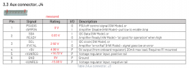
  • EVAL2_J4_voltages.png
    EVAL2_J4_voltages.png
    64.3 KB · Views: 86
  • EVAL2_PSU_voltages.png
    EVAL2_PSU_voltages.png
    68.7 KB · Views: 95
Unfortunately, the 1st round has not been successful. With all PSU voltages within specs, the amp refused to make switching, the output stage does not oscillate. I have sent the return request to https://www.soundimports.eu/en/ and would like to get a replacement unit.
Can't tell by the pics,but is pin 32 on J3 connector connected to ground?
My friend built a 3 channel one and it took him a while to find out that this pin should be grounded.
 
Can't tell by the pics,but is pin 32 on J3 connector connected to ground?
My friend built a 3 channel one and it took him a while to find out that this pin should be grounded.
Thank you, however this is controlled by the toggle switch on the input buffer/connector board. The switch controls the PSUDIS/AMPON signal and sets it Low when toggled towards 1ET400a module.

And, the VDR current is only 1.5 mA, though it should be 35 mA according to the specs. I suspect the MOSFET failure.

Edit: I have double checked the pin 32 of the main connector and it is properly driven by the S1 toggle switch on the input/connector board. So this is not the reason of the faulty module.
 
Last edited:
Received a replacement sample from Soundimports and it works fine. Nice customer service! Appreciated!
IMG_3124.jpeg

IMG_3125.png
 
Back
Top Bottom