• WANTED: Happy members who like to discuss audio and other topics related to our interest. Desire to learn and share knowledge of science required. There are many reviews of audio hardware and expert members to help answer your questions. Click here to have your audio equipment measured for free!

Compensating for mains and sub delay

I use minimum phase version of the calibration file

I just tried this out but the resulting phases and GDs make no sense.
why would the roll-off be minimum phase for example? it not rolling off because of added delayed signal like in a high-pass
 
what is going on at 100Hz btw @ErLan?

1689464170322.png
 
The burst tone plots @dualazmak shows ....

I assume and hope you are referring these my posts in my project thread;

- Precision measurement and adjustment of time alignment for speaker (SP) units: Part-1_ Precision pulse wave matching method: #493
- Precision measurement and adjustment of time alignment for speaker (SP) units: Part-2_ Energy peak matching method: #494
- Precision measurement and adjustment of time alignment for speaker (SP) units: Part-3_ Precision single sine wave matching method in 0.1 msec accuracy: #504, #507
- Measurement of transient characteristics of Yamaha 30 cm woofer JA-3058 in sealed cabinet and Yamaha active sub-woofer YST-SW1000: #495, #497, #503, #507
- Identification of sound reflecting plane/wall by strong excitation of SP unit and room acoustics: #498

I highly recommend you using Adobe Audition (I use ver.3.0.1 Build 8347.0) for time-amplitude (wave-shape) analysis and also for time-amplitude-frequency 3D-color-spectrum analysis.

I prepared my tone burst test signals using Adobe Audition and the ultra-high precision tracks of Sony's "Super Audio Check CD".

If you would be seriously interested in the tone burst signals I prepared as well as the intact tracks of "Super Audio Check CD", please simply PM me writing your wish.

Thank you very much for the kind offer @dualazmak !

I do believe it is already possible to achieve precision alignments using dedicated measurement software such as REW, SMAART, Acourate and FIR Designer... etc. However, like any other program, the internal workflow of it does take getting used to, and may not be as straightforward as one prefers.

Unfortunately, I do not use Adobe Audition and primarily use a Linux OS day to day.

A filtered wavelet plot generated in REW is actually simulating the same thing as your BW limited test tone burst signal recordings conveniently from a single swept sine measurement. Well, technically, it may not be exactly the same measurement acquisition technique -- but the results certainly can be close enough. Success or failure very much relies on the experience of the speaker system designer.


Just some interesting measurements I took some time ago of my S8 coaxial speaker:

1689472766233.png 1689472771176.png 1689472774257.png 1689472777139.png 1689472780537.png 1689472783719.png 1689472787183.png 1689472789970.png 1689472792533.png 1689472795324.png 1689472797667.png

Interestingly, I found out the real alignment programmed into the speaker's DSP is slightly worse axially in order to favor the overall off-axis response.
 
I just tried this out but the resulting phases and GDs make no sense.
why would the roll-off be minimum phase for example? it not rolling off because of added delayed signal like in a high-pass
Pictures speak better than words ;)

The only company I could find who measures calibration microphone phase response is ISEMcon and here's a graph from their measurements:

screenshot-2023-05-27-132900-jpg.61984


and here's my left speaker response measured by Umik-2 with default calibration file vs minimum phase version of the calibration file (IR delays auto-removed):

MicCal.jpg
 
Last edited:
I just tried this out but the resulting phases and GDs make no sense.
why would the roll-off be minimum phase for example? it not rolling off because of added delayed signal like in a high-pass

My UMIK-1 calibration data ends ~ at 10 Hz and 20 kHz. Generating a MP version in the 'Measurements actions' tab/window in REW does not produce a usable result. I believe a UMIK-2 would have more extended information and so does this even make up the difference? How do you generated your MP version for your mic calibration file @OCA ?

This has never been a concern for me since I usually focus phase matching/linearization where drivers/speakers sum. I also apply a HF and LF limit in REW. Also, the ISEMcon graph doesn't show any alarming gross differences either. Above 10 kHz doesn't concern me.

The ~90 degrees difference in @OCA's SPL & Phase graphs in the LF is rather more extreme.
I attached the originals as well just in case:


PS I checked all mic calibrating firms around Europe but NONE perform phase calibration.
 
Also, the ISEMcon graph doesn't show any alarming gross differences either.
That's quite a high-end €300 mic they're measuring in that graph though:

 
I attached the originals as well just in case:


PS I checked all mic calibrating firms around Europe but NONE perform phase calibration.

Aha, it looks like the slope applied on the end tails influences things! I didn't bother using that (tail ends) option when I was testing. The HF still doesn't really matter... difference is relatively small if we adjust the time offset to make phase flattest bet. 3-10 kHz or so, and I normally do not bother linearizing that far up. The rise in slope in the LF in your MP version correction file does look natural -- almost like a first order high pass... isn't that inaudible anyway?

1689530027195.png 1689530034130.png

Very interesting actually. In the end, final effect is probably not much/nada in terms of what we actually hear.
 
Aha, it looks like the slope applied on the end tails influences things! I didn't bother using that (tail ends) option when I was testing. The HF still doesn't really matter... difference is relatively small if we adjust the time offset to make phase flattest bet. 3-10 kHz or so, and I normally do not bother linearizing that far up. The rise in slope in the LF in your MP version correction file does look natural -- almost like a first order high pass... isn't that inaudible anyway?

View attachment 299494 View attachment 299495

Very interesting actually. In the end, final effect is probably not much/nada in terms of what we actually hear.
I agree HF is just a little off and LF is probably inaudible. I just wanted to emphasize that aiming for 0 deg phase throughout the full band 20-20kHz is a bit meaningless.
 
Aha, it looks like the slope applied on the end tails influences things!
I applied the tail slopes more carefully now. For 0 degree calibration I made one optimistic and one "pessimistic" tail because the original data seems to smooth just before the end on both sides which is probably an error on MiniDSP side. 90 degree cal file causes 100 degree shifts at 20kHZ, I should be more reluctant to use the mic pointing up!

I am using a beta REW version and it doesn't show below 10Hz for some reason but here you are:

1689536092689.png
 
Last edited:
I agree HF is just a little off and LF is probably inaudible. I just wanted to emphasize that aiming for 0 deg phase throughout the full band 20-20kHz is a bit meaningless.

We aren't really only interested in correcting for the speaker's high pass and crossovers, but some of the room's inevitable skew on the time domain. It all adds up... There certainly are cases where flattening the phase only (doesn't have to be completely "zero") sufficiently produces an obvious audible improvement. BTW, in that link, microphone position is pointed up. Phase appears "flattish" enough from the speaker's own internal FIR DSP correction. I don't think I should be concerned about the skew caused by my own microphone's response at all.

I like rePhase here a bit more than just letting REW apply the "phase inversion" as there's more control afforded to the user e.g. individual correction of drivers/channels.

In @ErLan's case, effectiveness of trying to force-flatten the phase with (what I assume is) the room's rather disproportionate skew is highly questionable. However, some amount of "correction" (with generous windowing) may be still worth trying out at least.
 
some amount of "correction" (with generous windowing) may be still worth trying out at least.

I used 5 cycles as suggested by @dasdoing to extract the excess phase. I then created two all-pass filters (using REW's EQ window and 'generate measurement from filters' button) eye-balling the GD peaks which I subsequently inverted. Thereafter I created a phase inversion above 400Hz -- however, the information is truncated and I don't really even think it's necessary here. Convolved the two filters to create a single one. Limited the left width/window to 171ms and exported the filter...

1689657062454.png


1689657066614.png


Approx. FIR delay should only be 171ms for this very simple "correction" filter.

1689657152143.png 1689657157625.png 1689657163621.png 1689657167859.png 1689657172177.png 1689657176802.png 1689657179822.png 1689657182325.png 1689657185303.png 1689657187896.png 1689657562784.png 1689657569435.png 1689658780767.png 1689658784314.png


What do you guys think of this simplified phase correction filter for @ErLan's right channel measurement?


Optimistically, I expect a subtle improvement in perceived transients in the bass area -- very likely above it and the midrange will still be exactly the same.


Maximum Q=4 for an APF is probably is still "acceptable" -- any more than that I wouldn't use...


------------

*Eh... might still have to use rePhase above 400Hz as I just noticed the ff. issue:

(again, which is kind of unnecessary already to begin with)

1689663267289.png


Phase inversion that I cut off below 400Hz (to slightly linearize mid-HF crossover) for some reason abruptly ends around 20Hz. Then again, the sweep data is bandwidth limited (20Hz-22kHz)... It's preferable to measure from 0 Hz to 24 kHz even if it's just for subwoofers.
 
Last edited:
  • Like
Reactions: OCA
I used 5 cycles as suggested by @dasdoing to extract the excess phase. I then created two all-pass filters (using REW's EQ window and 'generate measurement from filters' button) eye-balling the GD peaks which I subsequently inverted. Thereafter I created a phase inversion above 400Hz -- however, the information is truncated and I don't really even think it's necessary here. Convolved the two filters to create a single one. Limited the left width/window to 171ms and exported the filter...

View attachment 299890

View attachment 299891

Approx. FIR delay should only be 171ms for this very simple "correction" filter.

View attachment 299892 View attachment 299893 View attachment 299894 View attachment 299895 View attachment 299896 View attachment 299897 View attachment 299898 View attachment 299899 View attachment 299900 View attachment 299901 View attachment 299902 View attachment 299903 View attachment 299905 View attachment 299906


What do you guys think of this simplified phase correction filter for @ErLan's right channel measurement?


Optimistically, I expect a subtle improvement in perceived transients in the bass area -- very likely above it and the midrange will still be exactly the same.


Maximum Q=4 for an APF is probably is still "acceptable" -- any more than that I wouldn't use...


------------

*Eh... might still have to use rePhase above 400Hz as I just noticed the ff. issue:

(again, which is kind of unnecessary already to begin with)

View attachment 299908

Phase inversion that I cut off below 400Hz (to slightly linearize mid-HF crossover) for some reason abruptly ends around 20Hz. Then again, the sweep data is bandwidth limited (20Hz-22kHz)... It's preferable to measure from 0 Hz to 24 kHz even if it's just for subwoofers.
Nice filter, no pre-echo effects and ideal GD!

A polarity inverting rePhase linearization could give a head start:

GD.jpg

rePhase settings
eNptUl1v2zAM/CsGnzbAy+TYSbM8bthbBwR7LQKDtmhHqPUxSW6WFf3vo+ykTYq+BObdkUcd8wyN
/Vt3aojkA2wfHgByKFew3+fQkmFUmR62oJWUAzHXHqh9DKNmrGuElOVKFsuSSupku1l9W1eyFM3q
rpLrdVJ7G8LN+PvfWVYsM/n9q20jK5aVEJCLfT45F3PB5txDBjWxz8+dMk/kk7pT/mpaklmvMbKo
XGaNiiG73/34lWlrbPZpccSnz3DR1DwiKGtYWyzEhvEeVarEIplCT3/mkb1Hd6gDxchPDx9htUfz
CFuRg3q/jyYMoyfN0cH2GZqTwxAmaWu1IxMw0lRKjMgtZhyG/PZnP29W265jw7Qgb3dQkmqN/dQ7
Fe6AYR51Tid9RqXprbGo4CUHY5NlStc65tU/jHMMxhp6h9bdYK1n7st0CXCXUJwd0Kt4YortmAmo
3XDlxY0YL/j8n6k2YhoSbBeP6NMSnnbT2m9gHcbmfOcPyOubVYsyUWNzm3hEFxK/LjcVnBOQylP7
+kqvE35yyaO1/kxlrxfO4aiMtMd560Sj6Ud+L7z8B08jAww=


"Load settings from clipboard"
 
Last edited:
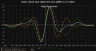
One more thing I am noticing in general is that phase curves do not really need to hug each other so tightly or perfectly while aligning. Rather, one should only try to get the aligned sum excess phase itself closer to zero or at least positive above zero. This will make the ringing ends of the step response balance/cancel each other out to form a more ideal shape.

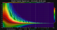
Avoiding negative excess phase also prevents pre-echo/ringing/delay artifacts from showing up in the wavelet spectrogram.

1689686977489.png

1689686984307.png


1689686994515.png


1689687497355.png


Caveat: there is one thing that can't be ascertained for sure from measurements made only at a single main listening position... and that is the off-axis behavior and spatial consistency of the aligned speaker system. This is yet one more thing that has to be verified as well by measuring off-axis directivity curves and/or spaced multi-point measurements.
 
Last edited:
Avoiding negative excess phase also prevents pre-echo/ringing/delay artifacts from showing up in the wavelet spectrogram.

I have been trying hard to find better workflows on my own, but as we all know, the more we get to the limit, the harder.
I will study your graphs tomorrow.
about avoiding negative excess phase: while the midrange is all cluttered even in my treated room and we better aim for a minimum phase behaviour, I don't think this is true for the bass. you see a minimum phase roll-off has group delay, as we all know. why should we aim for this? If we make the bass linear phase the exess phase will go into the negatives because the delay is expected. we are still linear phase though, and therefore there is nothing coming too early. rather we are now spot on.
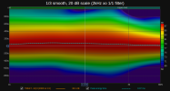
here is a correction I tried with excessphase and phase correction combination with 15fdw windows. It didn't work out (because of the midrange), but I can show you what I mean with the result:

wavelet before

1689732081781.png


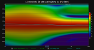
after

1689732108988.png


and this is the excess phase

1689732172329.png


I was wondering about this aparent contadiction before in this thread, but as I just explained, I am now convinced this is the ideal.

see:

1689732348124.png


very close to our utopic ideal that should be an dirac impulse:

1689732421131.png


if we make this sytem minimum phase in the bass this would be delayed.

again, this correction I am showing here doesn't work. I might be chasing the impossible here, but I just wanted to point out my thoughts about the minimum phase / linear phase thing
 
on a sidenote: I am avoiding the microphone phase issue atm (hate you for bringing that up @OCA lol). this might make the linear phase ideal in the bass ilusional, but I come back to this
 
  • Like
Reactions: OCA
I have been trying hard to find better workflows on my own, but as we all know, the more we get to the limit, the harder.
I will study your graphs tomorrow.
about avoiding negative excess phase: while the midrange is all cluttered even in my treated room and we better aim for a minimum phase behaviour, I don't think this is true for the bass. you see a minimum phase roll-off has group delay, as we all know. why should we aim for this? If we make the bass linear phase the exess phase will go into the negatives because the delay is expected. we are still linear phase though, and therefore there is nothing coming too early. rather we are now spot on.
here is a correction I tried with excessphase and phase correction combination with 15fdw windows. It didn't work out (because of the midrange), but I can show you what I mean with the result:

wavelet before

View attachment 300079

after

View attachment 300080

and this is the excess phase

View attachment 300081

I was wondering about this aparent contadiction before in this thread, but as I just explained, I am now convinced this is the ideal.

see:

View attachment 300082

very close to our utopic ideal that should be an dirac impulse:

View attachment 300083

if we make this sytem minimum phase in the bass this would be delayed.

again, this correction I am showing here doesn't work. I might be chasing the impossible here, but I just wanted to point out my thoughts about the minimum phase / linear phase thing

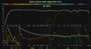
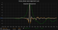
Actually, as with the potential mic phase calibration issue, there's some leeway here, and I think negative excesss GD in the very low bass appearing as a result of FIR phase linearization (if you want to apply it) might not always result in bad sound or unnacceptably non-ideal measurements (e.g. step response).

But, at the end of the day, (and I'm gonna sound uber-repetitive) you gotta verify it with critical listening tests afterwards to be sure you're not making things worse at least for your own ears' sake.

Those statements I made are just "general" mental notes from my own personal observations and what I've read that serve as overall guidelines and are not really always practical/applicable in every case or even 100% technically correct at all -- you can certainly object and question the veracity of it. I veer off the path of my own "set rules" quite a bit, actually. LOL.

Anecdotally, here and elsewhere, we've heard from lots of people that they don't like excessive phase linearization correction. Some research also suggests that negative GD (when synthetically applied e.g. from phase linearization and all pass filters) is more audible to us -- then again, we're already so used to positive GD and smearing of transient sounds from listening inside rooms. So... I'd rather be extra careful and have some energy smearing/ringing post or after t=0 than before -- if I can help it.
 
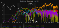
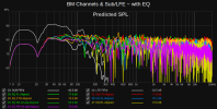
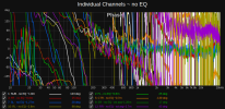
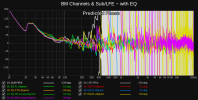
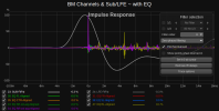
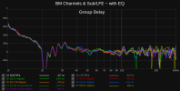
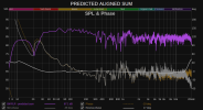
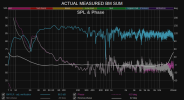
I've just finished "simulating" up update to my desk's nearfield 7.1 MCH system in REW using some of the things I've learned recently. I'm leaving a download link to the MDAT data if anyone wants to check the summed bass+mains alignments I cooked up. Some of results aren't nearly as ideal (surround channel measurements) ... but, overall I think it looks better than what I had before. Just don't mind the "apparent" uneveness in the overall EQ or SPL levels -- that needs a whole other explanation -- gist is basically it's the result of spatial averaging (MMM) and multi-point measurements, plenty of solo'd channel switching and listening for perceived tonality and loudness, reflection-decay analysis, distortion levels testing etc. Will have to program this whole new preset yet into JRiver and verify -- but I suspect it'll sound good.
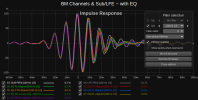
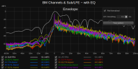
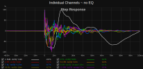
A quick measurements snapshot of my 7.1 MCH system's evolution from chaos to order. :)

1689749291738.png 1689749295046.png 1689749297827.png 1689749300941.png 1689749303234.png 1689749305485.png 1689749308432.png 1689749311089.png 1689749313420.png 1689749316088.png
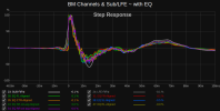


------------

The IIR and FIR EQ modeled from my unequalized subwoofer (raw response) turned out disappointingly a tad off so that some EQ re-adjustments were necessary, including increasing 16k to 32k taps with a maximum of ~341ms processing delay.

No adjustments were necessary for the mains.

Attached is a quick bass managed front left+right mains verification sweep measurement. Bass below 30 Hz or so actually is quite a bit variable throughout the course of a day (e.g. if doors and windows are open) and so it fluctuates -- this should be somewhat expected.


1689808704086.png 1689808713273.png
 

Attachments

  • Verifying summed prediction.mdat.zip
    2.5 MB · Views: 54
Last edited:
  • Like
Reactions: OCA
Back
Top Bottom