Hello again, OP
@ErLan,
Although really intensive and precise (and educational) discussions and actual practices were/are shared on this thread, I still do not fully understand how extensively/precisely you would like to solve
your "issues = delay between subwoofer(s) and other SP drivers" which you shared in your very first post.
I assume very simple/primitive pseudo-tuning of "group delay adjustment" or "time alignment" between
your sub-woofer(s) and
whole of other SP drivers may be possibly just enough in your own audio setup in your listening room acoustic environment.
If this would be the case, you can achieve "
quasi-time-alignment" using DSP software in PC, even for
single stereo-DAC plus
single stereo amplifier plus
passive LC(R) network SP system as shown in the diagram below.
I actually configured this scheme in my another small audio setup at upstairs office, and it works just fine enough (
i.e. acceptable compromisation) as expected for usual music listening enjoyments during my office work, even though not perfectly in-phase or linear-phase. In this case, maybe no intensive objective "measurements" would be needed, but just subjective hearing tests (using suitable "transient" music reference tracks,
e.g. ref.
here) would give you satisfactory improvements, if you can be relaxed and relieved with such "compromisation".
View attachment 302436
[/QUO
Thanks @dualazmak!
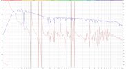
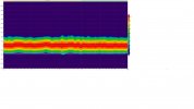
Indeed I still pending some exploration to converge. So far I mainly performed the invert phase approach (see above) that seems to markedly improve the performance, nevertheless there are some flaws that does requires further exploration (e.g. behavior 150Hz-300Hz, the ~370Hz peak, etc.)... but forced to take it slowely (surely relative to what I wish) due to personal availability.
W.r.t. method you shared above, if I understood correctly the essence is to break the signal to small pieces via. Adequate crossover, treat each saparately (mainly delay) and merge them back to a single output coming out of Lt/Rt.
Did I got it correctly?
If so, I conceptually tested it and it also being positive outcome, yet somewhat more combursome to create in EqAPO.
If not, I will be glad if you will further elaborate.

") ,
,