Now that’s a book to write! “Lessons from the Audiophile Battlefield”!Thanks for your kind comments. I look forward to writing everything that I've learned during 'UK Stage 1' of my business plan down for everyone to read for free on my website. Hopefully I'll be taking on new challenges for other products and assuming that I'm able to attain the competitive performance that I can get from phonostages I'll very much look forward to describing the design process for those too.
As far as protection goes I might have to take you up on that as quite a few people have tried to get me in trouble and cause issues for the company due to my technical transparency and competitive approach but so far haven't succeeded as I like to be very thorough and make everything air-tight. A disadvantage of this approach is that you have to tell the truth 100% of the time which is inconvenient in the short term and from a traditional 'audiophile marketing' perspective but is really starting to pay dividends.
One day I'll publish my collection of 'cease and desist' threat letters, along with a run-through of my first 2 years once I conclude the current phase of the business. Now and here is neither the time or place... Sadly they never seem to follow through on their promises of legal obliteration but I'm putting aside some of my revenue for a 'truth insurance' fund for when I start writing about good design practice with various examples of contemporary quackery to contrast.

-
WANTED: Happy members who like to discuss audio and other topics related to our interest. Desire to learn and share knowledge of science required. There are many reviews of audio hardware and expert members to help answer your questions. Click here to have your audio equipment measured for free!
You are using an out of date browser. It may not display this or other websites correctly.
You should upgrade or use an alternative browser.
You should upgrade or use an alternative browser.
Classic Audio MC Pro Phonostage Review
- Thread starter amirm
- Start date
Attack of the QuacksNow that’s a book to write! “Lessons from the Audiophile Battlefield”!

For this application the linear approach is certainly a lot less prone to trouble. You can generate internal +17V rails fairly easily and importantly keep them quiet at high frequency where opamp PSRR isn't as good as it is at mains frequency due to falling feedback factor as a result of frequency compensation.
For a standard 24V external SMPS (without any internal conversion in which case a 5V SMPS is best) you can only split the rails down to +-12V with a suitable rail divider and then you have to deal with quite a lot of noise current going into the ground path due to the EMI suppression cap that links the SMPS output to the mains to shunt away switching RF energy. It's a bit messy to say the least and you're limited to about 7V RMS output. If you do switching conversion internally with a 5V to +-15V module then you can get 9V RMS out but they're rather unstable and need a constant load.
That being said, many new products use custom SMPS modules internally that give very good results as is evidenced by measurements on the forum. For me at least with this product, reliabilty, simplicity, the absence of switching noise, isolation from the mains, and ease of repair should anything go wrong made the linear option the clear winner.
Having designed a couple of phonostages myself, I find this very interesting. I like the reasoning behind your choices and the end result is also very impressive.
Still, I took a quite different approach. This is the power supply part of my RH RIAA 3.0. First of all, almost all the components are SMD and in this case the PSU is a switched capacitor up & inverting IC with built in LDO regulators. It also gives clean and steady output (+15 V / -15 V) without injecting any audible or measurable noise to the amplifier stages.
I believe this approach is practically maintenance free with usable service life of at least 20 years. There's no electrolytic capacitors to give you trouble.
Like your product this one is also hand-soldered with lead-free tin that contains silver. It also has an active mute to stop any noises entering the rest of the system (realized by A1 and A3 in the picture).
Well, I prefer full SMD design myself and I also hand solder them on 4-layer boards, no problem at all and don't have to cut those extra wires after soldering.I just don't understand why these THT designs are still a thing. SMD parts are so much better. You can get 0805 SMD thin film resistors with 0,01% tolerance for the same price as 1% THT metal film resistor.
And you can get very high quality acrylic and PPS SMD film capacitors with 2% these days.
But THT design has its benefits too so it is more a matter of preference than anything else. I can of course say that fighting RF and other types of disturbances is easier with SMD but you can do it with THT as well if you know what you are doing. It is the board layout that is the most important detail.You are right about the PPS caps. The 2 % series is exactly what I'm using in my RIAA eq part. But 0.01 % thin film SMD resistors are very expensive. I don't think you really meant 0.01 % but rather 0.1 % which I'm using in all the amplifier sections? They are still quite expensive and cost more than typical 1 % metal film THT resistors.
There are two factors that decide how accurate your RIAA eq is:
- Circuit design. Wrongly calculated or inaccurate component values due to price reduction throw the eq accuracy immediately off.
- Parts tolerance. Even with 2 % caps and 0.1 % resistors, the RIAA curve can be off by several tenths of dB.
I just took a look at Michael's web site and was delighted to notice that his design philosophy matches my own in most cases. There are some differences too but perhaps I should start a thread of my own sometimes when I have time to avoid any more OT.
Generally I put the caps into matched groups but I've noticed that the accuracy of the '1%' through-hole resistors that I'm using is considerably better. The topology of the RIAA network as well (parallel) also plays a big part in averaging/mitigating component tolerance so the whole thing performs considerably better than you might expect in the worst case (which is a stastically unlikely outcome).Obviously @Michael Fidler has succeeded in both design and parts selection. It is simply impressive how well this amplifier performs and RIAA curve is practically flawless even with 1 % resistors (I bet they are hand picked). My own amp that is full SMD construction and has switching PSU reaches very similar performance but if I wanted to make it significanty better than this one it would be really hard, regardless of SMD construction or number of board layers.
As far as using SMPS goes I don't see the need to introduce it, so it's better to do without it. If we're going to the trouble of using THT then it's better to use more readily-available parts to 'future proof' the design. There is of course the need to dissipate about 1.5W or so inside the enclosure at idle but in this case the internal temperature stays well below 40c so all good.
That is not to say that SMPS is necessarily a bad thing if you have a limited amount of space and thermal headroom, or need to convert what's coming in to your power supply to DC with great efficiency. For through-hole it's difficult to keep the loop sizes low enough to avoid trouble even with a fair amount of PCB space available. In regards to a 15V internal rail it can certainly work well, but you'll be limited to about 9.2V RMS output unless you use rail-to-rail opamps which significantly limit your choices. Although if you structure the gain stages so that the final stage applies the last couple of decibels of gain and uses a rail-to-rail device then you can push past 10V RMS while still using 5532/4s, 2068s or any other suitable op-amp for the front end.
If I had to use an SMPS I would use a 5V input type and bring the rails up to about +-17V with a suitable DC to DC arrangement, hopefully with some isolation...
Last edited:
Are you kidding?Performance is well out of track in 2023.
Voted POOR.

MM Pro By Michael Fidler Phono Stage Reviewed - Audio Appraisal
As far as I can determine, £600 is enough to buy you the finest moving magnet phono stage currently in production. And that phono stage is the MM Pro by Michael Fidler. I will stand by that stateme…
AudioSceptic
Major Contributor
Has anyone also linked to their review of the MC Pro <https://www.audioappraisal.com/classic-audio-mc-pro-moving-coil-phono-stage-reviewed/>?MM Pro By Michael Fidler Phono Stage Reviewed - Audio Appraisal
As far as I can determine, £600 is enough to buy you the finest moving magnet phono stage currently in production. And that phono stage is the MM Pro by Michael Fidler. I will stand by that stateme…www.audioappraisal.com
AudioSceptic
Major Contributor
J
Could it be that things really are changing at last and honest, objective reviews, as we see at ASR, Archimago, and Audio Appraisal, are gaining ground against the borderline-dishonest delusional nonsense that's dominated for so long?
I have to quote this snippet from another review at that site.Has anyone also linked to their review of the MC Pro <https://www.audioappraisal.com/classic-audio-mc-pro-moving-coil-phono-stage-reviewed/>?
But there’s a great need for honest, unbiased reviews in this industry. I firmly believe that hi-fi should be accessible to everyone and that you shouldn’t have to wade through marketing hyperbole, disingenuous advertising, BS audiophile pseudoscience and brand snobbery when you’re trying to make a purchasing decision.
Could it be that things really are changing at last and honest, objective reviews, as we see at ASR, Archimago, and Audio Appraisal, are gaining ground against the borderline-dishonest delusional nonsense that's dominated for so long?
AudioSceptic
Major Contributor
There is now a HP/pre-amp, the Spartan 30 <https://michaelfidler.com/products/spartan/spartan-30-headphone-amplifier/>. I'd prefer remote volume control for pre-amp use, but even just for the HP amp it's good value for SOTA performance.I notice a few people mentioning the price, I'm clueless about anything to do with vinyl so I had a look at mc phonostages on a popular retailer's website and ordered by price. Going from lowest (£64) to highest (£12,500!! although the penultimate was about 5k), £650 gets you about a quarter of the way down the page. I realise this isn't the best way to judge value but it's the best I could do without knowing what I'm looking at, it doesn't seem particularly outrageous to me. The product seems to be well designed and of high quality. It looks great in my opinion, especially inside.
I think it's worth mentioning that all of these products are hand built and soldered by one chap in his spare room in Kent (UK), then tested to spec on an analyser, in fact he even provides a picture of said state of the art spare room on his website:
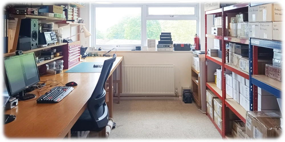
So obviously there is going to be some premium compared to mass machine produced devices made in countries that have far lower costs all around. I would also expect this to have a good level of reliability (some thermal testing is in one of his latest facebook posts) and customer service. If anything goes wrong I know I can contact the guy and I haven't got to ship anything half way around the world, appreciate this isn't the case for those in the US/elsewhere.
I also think it's worth shouting out his website as there are very detailed explanations and measurements of each product as well as some quite lengthy articles for those interested: https://michaelfidler.com
He also has a Facebook page where he seems to be very transparent and willing to answer questions, as well as giving previews of upcoming stuff etc: https://www.facebook.com/mfidleraudio
I realise this probably reads like I'm a massive shill or have some sort of affiliation. Believe it or not I actually hadn't heard of him until googling from this review. I was just quite impressed as often a lot of these types of products made by a small company get into a lot of the subjective nonsense and don't measure that well.
Also will admit I'm a bit biased towards a small manufacturer and it being made somewhat locally! I don't have any use for this but will definitely keep an eye on the upcoming headphone amp.
Ooh thanks for the heads up, looks really nice. I noticed on a facebook comment he said there will probably be a pro series preamp with balanced inputs in 2025, perhaps that may have remote volume control?There is now a HP/pre-amp, the Spartan 30 <https://michaelfidler.com/products/spartan/spartan-30-headphone-amplifier/>. I'd prefer remote volume control for pre-amp use, but even just for the HP amp it's good value for SOTA performance.
It most certainly will!Ooh thanks for the heads up, looks really nice. I noticed on a facebook comment he said there will probably be a pro series preamp with balanced inputs in 2025, perhaps that may have remote volume control?
Awesome, another thing to look forward to. Thanks for the response!It most certainly will!
Very nice.There is now a HP/pre-amp, the Spartan 30 <https://michaelfidler.com/products/spartan/spartan-30-headphone-amplifier/>. I'd prefer remote volume control for pre-amp use, but even just for the HP amp it's good value for SOTA performance.
- Joined
- Dec 18, 2021
- Messages
- 186
- Likes
- 277
I have similar experiences with Michael. He is very responsive on any question you ask or any comment you have. He is very open about his designs and choices he made. No BS at all!I notice a few people mentioning the price, I'm clueless about anything to do with vinyl so I had a look at mc phonostages on a popular retailer's website and ordered by price. Going from lowest (£64) to highest (£12,500!! although the penultimate was about 5k), £650 gets you about a quarter of the way down the page. I realise this isn't the best way to judge value but it's the best I could do without knowing what I'm looking at, it doesn't seem particularly outrageous to me. The product seems to be well designed and of high quality. It looks great in my opinion, especially inside.
I think it's worth mentioning that all of these products are hand built and soldered by one chap in his spare room in Kent (UK), then tested to spec on an analyser, in fact he even provides a picture of said state of the art spare room on his website:
So obviously there is going to be some premium compared to mass machine produced devices made in countries that have far lower costs all around. I would also expect this to have a good level of reliability (some thermal testing is in one of his latest facebook posts) and customer service. If anything goes wrong I know I can contact the guy and I haven't got to ship anything half way around the world, appreciate this isn't the case for those in the US/elsewhere.
I also think it's worth shouting out his website as there are very detailed explanations and measurements of each product as well as some quite lengthy articles for those interested: https://michaelfidler.com
He also has a Facebook page where he seems to be very transparent and willing to answer questions, as well as giving previews of upcoming stuff etc: https://www.facebook.com/mfidleraudio
I realise this probably reads like I'm a massive shill or have some sort of affiliation. Believe it or not I actually hadn't heard of him until googling from this review. I was just quite impressed as often a lot of these types of products made by a small company get into a lot of the subjective nonsense and don't measure that well.
Also will admit I'm a bit biased towards a small manufacturer and it being made somewhat locally! I don't have any use for this but will definitely keep an eye on the upcoming headphone amp.
AudioSceptic
Major Contributor
That will cost a *lot* more, though, > £1k?It most certainly will!
Probably in the region of 2-2.5k, as it will feature 4 RCA inputs, 4 XLR inputs, defeatable tone controls, full size enclosure, relay volume control, level meters, stronger headphone amplifier...That will cost a *lot* more, though, > £1k?
AudioSceptic
Major Contributor
Someone suggested earlier in this thread that your products should come with transparent tops to show off the ultra clean circuitry. Seriously, might that be an option, or is it out of the question for cost and/or performance (EMF screening, etc.) reasons?Probably in the region of 2-2.5k, as it will feature 4 RCA inputs, 4 XLR inputs, defeatable tone controls, full size enclosure, relay volume control, level meters, stronger headphone amplifier...
ban25
Addicted to Fun and Learning
- Joined
- Nov 5, 2022
- Messages
- 753
- Likes
- 746
It would be cool indeed!Someone suggested earlier in this thread that your products should come with transparent tops to show off the ultra clean circuitry. Seriously, might that be an option, or is it out of the question for cost and/or performance (EMF screening, etc.) reasons?
I did think about this a while ago, and it is possible to source EMI shielded custom glass pieces for surprisingly little as long as the quantity is in the triple digits. However, it seems that this would have to be at the top of the product to give a good view (maybe some space on a full-size enclosure on the front panel), which would probably get broken very easily when stacking units on top of each other. At the moment, dropping the cases just dents the corners a little, but doesn't render the units inoperable.Someone suggested earlier in this thread that your products should come with transparent tops to show off the ultra clean circuitry. Seriously, might that be an option, or is it out of the question for cost and/or performance (EMF screening, etc.) reasons?
For the time being, it doesn't seem like a great idea to devote time to, but perhaps in the future, with a new enclosure style, it might be worth looking into again. At the moment, I'm just trying to concentrate on the electronics and keep the enclosure design relatively simple. For a 'high end' type of product it's probably a very good idea with a few strategically placed LEDs, but I'm not selling things for four figures (yet).
Similar threads
- Replies
- 24
- Views
- 3K
- Replies
- 4
- Views
- 3K
- Poll
- Replies
- 238
- Views
- 60K
- Poll
- Replies
- 70
- Views
- 16K