• WANTED: Happy members who like to discuss audio and other topics related to our interest. Desire to learn and share knowledge of science required. There are many reviews of audio hardware and expert members to help answer your questions. Click here to have your audio equipment measured for free!

Chinese DriveHack PA2 Hopeful Improvements

deadwood83

Member
Joined
Sep 1, 2022
Messages
91
Likes
160
The story starts with me originally ordering a cloned Venu360 since some posters indicasted they seemed to be units which 'left' the DBX facility.

The seller did not have any VENUs (which was good after I saw Amirm's review) and the seller offered to sent two driverack PA2 clones instead.


They showed up and I was quite happy with them until...... Until I measured them. Damn you Cosmoas ADC!

The poor measurements, <60dBr multitone, <72dbR 1kHz FFT; left me shocked. I had to take a look inside. And inside I went.
There I found more Harmann markings, more obviously Harmann boards, genuine components, etc. ..... and also a ton of X7R or X5R resistors instead of NPO/C0G. The distortion was primarily due to odd-order harmonics which were MASSIVE.

This lead me eventually to this article. https://www.edn.com/signal-distortion-from-high-k-ceramic-capacitors/ (it has pictures!)

At this point I was about ready to get a miniDSP Flex, but my amps take balanced only, and my subs require discrete inputs (not line level) and they need some PEQ of their own. So to get an equivalent setup, I could get either two flexes, a flex and a miniHD for the subs, and then what would I do with my Loxjie D40? Hmmmmmmmm.

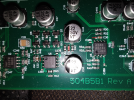
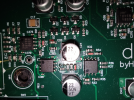
So onward I went, into the belly of the beast, carefully plucking each cap, measuring it, notating on my prepared photos, moving it aside, plucking the next, etc. This is a cheap Honeytek capacitance meter so the low pF readings are maybe +-10%, but the values showed up in various places on the Cirrus Logic datasheet for the audio codec.

I have ordered all new C0G and NP0 from LCSC consisting of Yageo and Murata units. Digikey/Mouser has nothing even close to a full BOM required. I ordered at least 2x as many as required for each part number.

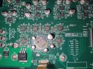
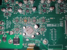
Please enjoy the photos attached as I attempt to reverse-engineer this circuit to see if my hunch bears any fruit. The third and fourth images have some veeeery small text which will require some zoom to read. They mark out some traced circuits as well as some labels and pinouts It would appear there are three JRC4580 opamps between any in/output and the ADSP/Codec.


I'm sure the MiniDSP is a better product, of that I have no doubt. But I just need this to have a higher SINAD than my PA3s amplifiers. This was about $220 USD and if the caps bring it in-line with a genuine unit (93 SINAD) then I will be pleased as punch. Stay tuned for results.

Whoops! Totally forgot some sources. Look at all the C0Gs in this crappy screen from a crappy "repair" video. (YouTube)
1668233974052.png

I have nothing close to that many pearly whites in my units.

On the flex front, $600 USD is too rich for my blood (considering they use the same core componentry namely ADAU-21489, plus the $75 markup for different outputs, plus the constant $200 Dirac upsell) combined with needing a whole other interface chain just to add my subs, and no option for a balanced flexEight. If I can get the HackRack to hit 90 SINAD will I really ever hear the extra 10-20dB noise floor? Not with a projector and 1L mini pc in the same room and a refrigerator 40 feet away. I have no idea why they didn't offer 6 analog outputs unless they only use a 4-channel codec / dual 4 channel dac/adc which is then just split to make the 8. Oh; actually that's probably exactly it. But it is still slightly perplexing to me since they seem to cater to an audience which would run more than just 2-way speakers. Four channels is not enough for a 2-way + sub, four is too many for a simple passive xover 2.1. Four is overkill for a studio monitor setup. Maybe they were targeting people with passive stereo but two subs? Not sure, but four just seems like an odd choice for output channels. (Can you tell I want to buy the flex but just cannot rationalize it? I like it and I want to buy it, but it just doesn't make sense for my setup).
 

Attachments

  • IMG_20221111_210802.jpg.png
    IMG_20221111_210802.jpg.png
    2.9 MB · Views: 306
  • IMG_20221111_210746.jpg.png
    IMG_20221111_210746.jpg.png
    3 MB · Views: 298
  • IMG_20221106_220946.jpg
    IMG_20221106_220946.jpg
    353.4 KB · Views: 320
  • IMG_20221106_220946.jpg.png
    IMG_20221106_220946.jpg.png
    2.6 MB · Views: 322
Last edited:
OP
D

deadwood83

Member
Joined
Sep 1, 2022
Messages
91
Likes
160
Throwing down some baselines on the as-delivered product. Nothing changed here. I know DBX/Harman has been trying to crack down on these but honestly, they don't need to worry much.

@pkane already made a lovely writeup on an original unit. I'm not sure if these ali units are clones or just devices which failed DBX standards. I know Kyocera makes some Class I caps in tan. Maybe they flirted with a different/cheaper supplier and just scrapped the batch? No idea. Anyway, it makes the double cost of the original unit (With Amazon Prime shipping) look decent. All mfg-marked components bear the proper brand names for a genuine device (including all Neutrik XLRs).

All readings taken with a Cosmos ADC set to 6.7V input sensitivity. This device has some passive gain even with xover set to unity passband as below:
1668480460103.png


I can measure the Loxjie D40 in 6V mode on the Cosmos without any clip indicators lighting. Once I insert this device, full signal will light up clip warnings in Multitone.

Loxjie D40 feeds its left channel into an XLR y-cable which enters both the R and L channels of the device in question. Single XLR cables go from the 'High' outputs to the L and R of the Cosmos ADC.

I tried to take mostly the same measurements we are used to seeing in reviews.

Kicking things off with the 1kHz FFT we see the odd harmonics which made me dig into thi.

d40_pa2_1khz_-1.JPG


These persist at different levels of DAC volume attenuation and only disappear if the generator signal is dropped by ~25dBFS. We'll see that number come up again later. The channel imbalance made me question my Cosmos ADC but swapping to a Y-cable so that only the left channel feeds both Cosmos L and R the channels read identically. This is not a Cosmos issue.

Multiply the number of tones and, well, look for yourself. Fewer than 10-bit distortion free range. I think some speakers can return better FFTs. The title was meant to be -53.0 but I was lazy on the 0. We see the imbalance persist.

d40_pa2_multitone_multitone.JPG


If we look a little more at the channel imbalance with an RMS level vs frequency sweep it makes sense. The left channel has more variability but also less noise. The right channel has quite poor separation from the Atmel FPGA circuitry so perhaps there is some minor influence.
d40_pa2_frequency_sweep_amplitude.JPG


Linearity is... also poor. We can see linearity eclipse the 1dB mark by -60dBFS. It seems Amir will call it a loss at 0.5dBFS which is abound -40dBFS on this sample.

d40_pa2_linearity_sweep.JPG


IMD VS Level shows a recurrence of that -25dBFS signal point. The D40 has some IMD 'ESS Hump' but this Chinese unit does not even come close to being quiet enough to show it. More channel imbalance. At least it is superbly predictable.
d40_pa2_imd_vs_level.JPG


Moving on we can look at frequency dependence. This is also a really alarming result. This unit has had issues with ground before. I am not brave enough to float the ground, but perhaps the assembly quality is partly to blame. While disassembling unit 2, I noticed that there was absolutely no attempt to remove chassis paint at ground points. The entire concept of 'grounding' seems to depend on whether the threads securing board to chassis were cut before or after paint.

d40_pa2_frequency_sweep_thdn.JPG


Combining the above two plots we can look at SINAD versus level. It's not great.
d40_pa2_sinad_vs_level.JPG


The curves are very pretty, but the numbers they show are... disappointing. Sometimes 'clones' are just a literally identical product sold by an assembler without scruples. Sadly for me but fortunately for DBX, this is not the case here.


I'm not sure if anybody else likes PCB photos but I sure do. The missing polycap was my fault sort of. The caps weren't soldered particularly flat to the soldermask so they aren't securely mounted, but I also left this without the lid on in a project pile with other items on top of it for a month+. The missing cap with its associated pads is taped inside the chassis. I'll repair it just for practice.


Outputs/Codec/DSP Chip
1668483118313.png


And the input section:
1668483336855.png


Every signal goes through exactly three JRC 4580s on either side of the codec. I do appreciate the symmetry and the orderly layout of most of the board.

On one last whim, I tried running a SINAD vs level with the gain switch set to -10dBV. The DBX version can take up to +20dBu signals or something equally ridiculous so I thought perhaps it just wanted a little extra spice. My hopes were dashed.

1668483996125.png


This is the signal level where it takes a massive downward turn.

1668484190966.png


I think I can accomplish the swaps this weekend. If it's just as bad then well..... My sub does have line level inputs and a tunable crossover knob. It will be extremely tedious to tune compared to being able to RDP into the host PC with mic and being able to network connect to the DriveThing but I guess I'll dig up $600 USD for a miniDSP Flex balanced + new cable connectors.

Oh and I almost forgot jitter. That is one very redeeming quality of this device in my opinion. I would love to use Multitone for everything because it is so much faster and more stable than REW but the output zoom options are not quite on the same level as its significantly older counterpart.
d40_pa2_jitter.JPG
 

pkane

Master Contributor
Forum Donor
Joined
Aug 18, 2017
Messages
5,699
Likes
10,386
Location
North-East
Throwing down some baselines on the as-delivered product. Nothing changed here. I know DBX/Harman has been trying to crack down on these but honestly, they don't need to worry much.

@pkane already made a lovely writeup on an original unit. I'm not sure if these ali units are clones or just devices which failed DBX standards. I know Kyocera makes some Class I caps in tan. Maybe they flirted with a different/cheaper supplier and just scrapped the batch? No idea. Anyway, it makes the double cost of the original unit (With Amazon Prime shipping) look decent. All mfg-marked components bear the proper brand names for a genuine device (including all Neutrik XLRs).

All readings taken with a Cosmos ADC set to 6.7V input sensitivity. This device has some passive gain even with xover set to unity passband as below:
View attachment 243402

I can measure the Loxjie D40 in 6V mode on the Cosmos without any clip indicators lighting. Once I insert this device, full signal will light up clip warnings in Multitone.

Loxjie D40 feeds its left channel into an XLR y-cable which enters both the R and L channels of the device in question. Single XLR cables go from the 'High' outputs to the L and R of the Cosmos ADC.

I tried to take mostly the same measurements we are used to seeing in reviews.

Kicking things off with the 1kHz FFT we see the odd harmonics which made me dig into thi.

View attachment 243403

These persist at different levels of DAC volume attenuation and only disappear if the generator signal is dropped by ~25dBFS. We'll see that number come up again later. The channel imbalance made me question my Cosmos ADC but swapping to a Y-cable so that only the left channel feeds both Cosmos L and R the channels read identically. This is not a Cosmos issue.

Multiply the number of tones and, well, look for yourself. Fewer than 10-bit distortion free range. I think some speakers can return better FFTs. The title was meant to be -53.0 but I was lazy on the 0. We see the imbalance persist.

View attachment 243404

If we look a little more at the channel imbalance with an RMS level vs frequency sweep it makes sense. The left channel has more variability but also less noise. The right channel has quite poor separation from the Atmel FPGA circuitry so perhaps there is some minor influence.
View attachment 243406

Linearity is... also poor. We can see linearity eclipse the 1dB mark by -60dBFS. It seems Amir will call it a loss at 0.5dBFS which is abound -40dBFS on this sample.

View attachment 243409

IMD VS Level shows a recurrence of that -25dBFS signal point. The D40 has some IMD 'ESS Hump' but this Chinese unit does not even come close to being quiet enough to show it. More channel imbalance. At least it is superbly predictable.
View attachment 243411

Moving on we can look at frequency dependence. This is also a really alarming result. This unit has had issues with ground before. I am not brave enough to float the ground, but perhaps the assembly quality is partly to blame. While disassembling unit 2, I noticed that there was absolutely no attempt to remove chassis paint at ground points. The entire concept of 'grounding' seems to depend on whether the threads securing board to chassis were cut before or after paint.

View attachment 243410

Combining the above two plots we can look at SINAD versus level. It's not great.
View attachment 243415

The curves are very pretty, but the numbers they show are... disappointing. Sometimes 'clones' are just a literally identical product sold by an assembler without scruples. Sadly for me but fortunately for DBX, this is not the case here.


I'm not sure if anybody else likes PCB photos but I sure do. The missing polycap was my fault sort of. The caps weren't soldered particularly flat to the soldermask so they aren't securely mounted, but I also left this without the lid on in a project pile with other items on top of it for a month+. The missing cap with its associated pads is taped inside the chassis. I'll repair it just for practice.


Outputs/Codec/DSP Chip
View attachment 243419

And the input section:
View attachment 243420

Every signal goes through exactly three JRC 4580s on either side of the codec. I do appreciate the symmetry and the orderly layout of most of the board.

On one last whim, I tried running a SINAD vs level with the gain switch set to -10dBV. The DBX version can take up to +20dBu signals or something equally ridiculous so I thought perhaps it just wanted a little extra spice. My hopes were dashed.

View attachment 243422

This is the signal level where it takes a massive downward turn.

View attachment 243423

I think I can accomplish the swaps this weekend. If it's just as bad then well..... My sub does have line level inputs and a tunable crossover knob. It will be extremely tedious to tune compared to being able to RDP into the host PC with mic and being able to network connect to the DriveThing but I guess I'll dig up $600 USD for a miniDSP Flex balanced + new cable connectors.

Oh and I almost forgot jitter. That is one very redeeming quality of this device in my opinion. I would love to use Multitone for everything because it is so much faster and more stable than REW but the output zoom options are not quite on the same level as its significantly older counterpart.
View attachment 243426
Nice work, @deadwood83 ! Certainly looks like other than jitter, the unit is no competition to the original it was trying to clone. Curious to see your improvements as you make and measure them.

Oh and I almost forgot jitter. That is one very redeeming quality of this device in my opinion. I would love to use Multitone for everything because it is so much faster and more stable than REW but the output zoom options are not quite on the same level as its significantly older counterpart.
Which of the zoom options are missing in Multitone? I'm all for adding improved functionality :)

Here are some of the more common mouse/keyboard tricks for zooming around on any of the plots:
https://www.audiosciencereview.com/...loopback-analyzer-software.27844/post-1379488
 
OP
D

deadwood83

Member
Joined
Sep 1, 2022
Messages
91
Likes
160
Ah, for the jitter in REW I will use the holding center mouse button and expanding/contracting each axis so I can fit full vertical data with a much smaller time scale. Basically plot something in the latest REW release and hold down mouse wheel button and move the mouse up/down/left/right. Ctrl+RMB + drag an area is similar but if I get that wrong it feels like I need to reset axes and try again compared to just making a few small adjustments.

I'm super curious if the re-cap to proper dielectric will make any difference. My 1kHz FFT bears a striking resemblance to the EDN paper's findings on 0603 X7Rs used improperly.

contenteetimes-images-01steve-t-sig-dist-hi-k-cer-caps-f3l.jpg


Also the noise versus SNR in that same measure is suspect.
1668521908588.png


Add I may need to walk back my statemenbts about the problem not being with my Cosmos ADC because I ran a D40-only quick test using 512kfft 4 averages every 1dB of level last night. I may need to reach out to Ivan on Discord.

D40 only, SINAD vs level at 6.7v sensitivity. The numbers are better at 4.5V sensitivity because the cosmos does seem to have some suceptibility to environmental noise.
1668522026577.png


Edit: The ADC was in mono mode. Oops.
 
Last edited:

Neddy

Addicted to Fun and Learning
Joined
Mar 22, 2019
Messages
756
Likes
1,031
Location
Wisconsin
Wow. Just wow. Popcorn loaded.:rolleyes:
 
OP
D

deadwood83

Member
Joined
Sep 1, 2022
Messages
91
Likes
160
"and also a ton of X7R or X5R resistors instead of NPO/C0G" . Is capacitor the right term, i never heard of resistor with such ratings. Great write up
You eagle eye. I even edited some spelling and missed that again. :facepalm: Sadly I can no longer edit my first two posts so my shame shall be eternal, but it is hardly the greatest eternal shame I have so it's alright. Thank you for pointing that out for future readers.

Yes, capacitors. I have never bought into the passive component swap craze that is a lot of audio circles but a post from AnalogSteph on the Behringer review caught my attention and further searching turned up that EDN article with actual measurements. TI whitepapers always stress dielectric selection but they never say why, and even their OPA702? 602? 206?(unsure) whitepaper which has a whole section on capacitor dielectrics never covers exactly what you would see as a way of diagnosing improper dielectric usage. It just says "see, higher THD+N according to package size and dielectric."

Perhaps it is something basic all EE's (electrical engineers) or SA's (signal analysts) are taught in school but I can excuse myself with "well, I was trained as an ME so I am clueless." :p

Also, there is nothing wrong with my ADC. After the WIndows 22H1 update, it reset input level to 100% which sets the ADC to mono mode. The Cosmos ADC can have +-3dB noise floor in mono mode (but you get better measurements on the channel with the lower floor) and with the level at 100%, the driver sets it to mono mode. It is safe to say that there is no channel imbalance on the ChiRack PA2. I was just a little careless.
 

5th element

Member
Joined
Feb 2, 2019
Messages
42
Likes
152
Yes it should be absolutely noted that any dielectric, other than NP0/C0G, is not suitable for a position in the signal path, especially around the corner frequency of the filter they are making.

Of course there are othe sources of 3rd order, and then other odd order harmonics, in audio equipment but this is one of them. It will be interesting to see the results of the cap swap.
 

kipman725

Active Member
Joined
Jul 6, 2020
Messages
255
Likes
224
Yes it should be absolutely noted that any dielectric, other than NP0/C0G, is not suitable for a position in the signal path, especially around the corner frequency of the filter they are making.

Of course there are othe sources of 3rd order, and then other odd order harmonics, in audio equipment but this is one of them. It will be interesting to see the results of the cap swap.
Depends, if the DC bias voltage is large relative to the signal level the other dielectrics can work. There are plenty of older amplifiers that used electrolytic capacitors as coupling capacitors. I would avoid doing so though ;)

That the nosie and jitter are low indicates that the capacitors have a good chance of been the only problem. Posible that a component sourcing error lead to a bad batch of units which then have ended up selling in secondary market?
 
OP
D

deadwood83

Member
Joined
Sep 1, 2022
Messages
91
Likes
160
Supplies arrived.

I have a T-12 iron with a few tiny tips, and I ordered two syringes of MG Chemicals flux paste. That alone makes this build way classier than the 20 year old Radio-Shack 60/40 solder roll I typically use.
1668658823622.png

I know these parts are tiiiiny (0603) and my solder paste has an expiration date of about.... actually exactly two years minus three days ago (Nov 19, 2020). I threw a little IA into it and packed half a mL into a syringe.
1668658793258.png

Unit one, ready to operate.

First thing's first. Let's get this out onto a tray.

IMG_20221116_200348.jpg


Nice.

T-12 C tip: installed.
Paste: on standby
Flux: overflowing, just how MG intended it.

Even though I should already know all the values from my previous measurements, I will not take for granted that the assembler just got sloppy. So I measure... Every. Single. Capacitor. I. Remove. This is very slow work for me.

I started with the input section to get my heat control and timings down before moving right next to the codec. First the left:

IMG_20221116_195857.jpg.png


Then the right:
IMG_20221116_195851.jpg.png


C13 and C12 both look preeeeeety C0G/NP0-ish next to the original caps, so I left them alone.

After some concentration and eyestrain, I have my first results. I should have bought a desk lamp. I think this same thought every single time I solder. I need either a lamp, or a jeweler's headset. That said, I am very proud of myself.

First the left:
1668658987161.png


Then the right.
1668659036830.png


Wow! C12 and C13 look much less like the proper type now. I should remove one, measure, and see if any of my values match it. Sadly there are several of these pale brown caps that I did not previously consider; due to them looking much more like a white ceramic next to the original units. Oof. Perhaps I can find some which happen to be the same value as on my donor SMSL M8 board and in positions where a perfect <1% match is not required.

To be continued.
 
OP
D

deadwood83

Member
Joined
Sep 1, 2022
Messages
91
Likes
160
Capacitors: All swapped. I hope folks with a proper setup don't get this back and neck pain every time! :D
To do: Fix grounding. But it's 11:30PM. Maybe tomorrow. Then some testing.

Codec area now:
IMG_20221116_232612.jpg


Lows:
lows.jpg


Mids:
mids.jpg


Highs:
highs.jpg


Turns out I DID order those extra caps for the inputs. So those got swapped too. .

Look at that beautifully cut screw. That takes talent. Also the grounding may as well not exist.

ground.JPG
 

Berwhale

Major Contributor
Forum Donor
Joined
Aug 29, 2019
Messages
3,954
Likes
4,962
Location
UK
Sadly I can no longer edit my first two posts so my shame shall be eternal

FYI - I believe a small donation to ASR will earn you 'edit forever' rights along with a 'Forum Doner' badge. See the 'Donations' link at the top of this page (between 'What's New' and 'Members' menus).

Also, nice work!
 
OP
D

deadwood83

Member
Joined
Sep 1, 2022
Messages
91
Likes
160
Some preliminary results are in.

The major question is: Did the modification help or hurt?

We can see that it definitely helped. The 1k FFT shows we now have extra headroom. About 8dB of it. Did it help as much as I wanted? Hmmmm, no, not really. Oddly, noise shows higher despite visibly less harmonic distortion.

pre_V_post_1k_pa2.JPG


Where we see a massive improvement is in the multitone! Holy smokes. Almost 13dB of distortion free range. That's like getting two bits extra. The high end is especially different. This shows that the next target of my investigation will be the midband.

multitone_pre_v_post_pa2.JPG


Frequency dependence has also improved massively, though we again see mids and a ~6k spike influencing it. The graph looks worse until you consider that the entirety of the post-OP data would fit below the pre-OP data.

freq_dep_before_v_after.JPG


I did some playing around, and I think I have homed-in on the target. Using the dBFS modulation within both the driverack itself and within Multitone, I was able to try out different combinations of gain. I believe the core issue lies within the input section. IF I dropped multitone output to -25dBFS and set the driverack to boost all frequency ranges in the crossover by 20dBFS, we should wind up at a net -5dBFS. I then set the driverack back to 0db gain and set Multitone to -5dBFS and ran the test again.

dspvs_input1.JPG

dspvs_input2.JPG


We can see that both scenarios reported an output within .03dBr of each other, and we can see the noise floor of the internal DSP boost being lifted... but we also see the THD go down in direct proportion to the point where you get almost 12dB more distortion free range by having the DSP boost to max. I believe it is a more accurate representation of the output stage capabilities (minus the harmonics which are just wildly above the noise floor).

Following that, I started to map out the input stage. It is... very tedious. One interesting observation is that the Cirrus codec takes balanced inputs, but the PA2 architecture first step is to convert BAL to SE on one half of the opamp, use the other half as what looks like a voltage follower, pass that through a series of switched diodes which I think are clamping to 5Vpp, convert back to balanced, then finally send it out to the codec. But I have not yet been able to trace the switched diode center contacts to anything useful. This board is four layers which makes it a little more difficult to trace anything.

1668741498733.png


I cannot, for the life of me, figure out what C26 even does.
 
OP
D

deadwood83

Member
Joined
Sep 1, 2022
Messages
91
Likes
160
Nice work.
Just getting caps closer to their specified value should help with performance.
Aye. I would love an original schematic of the PA2. At heart it is not so different than the miniDSP flex, and the Cirrus Logic codec inside had lower numbers than a TI PCM5102A which is fairly impressive to me considering the age of both the PA2 design and the codec chip itself. I am usually tickled pink when a design is a series of carefully interfaced whitepaper examples. In my experience those tend to work very well. Similar story with EVMs just reintegrated to form a cohesive unit. An EVM (at least from TI) is basically a show of how nice a chip can be. I have a hunch that Infineon and Cirrus are similar. Slight shame to see this deviate so much from Cirrus' recommended design. They have literally all the parts there.

1668742664584.png
 
OP
D

deadwood83

Member
Joined
Sep 1, 2022
Messages
91
Likes
160
Uh-oh. Preview of what is to come. Did I just exceed the genuine PA2? Ignore the chart title. I'll set up a sweep.


1668758546353.png
 
OP
D

deadwood83

Member
Joined
Sep 1, 2022
Messages
91
Likes
160
Instructions: Swap caps for NP0/C0G.

MAKE SURE TO SWAP CAPS C26 AND C17 AS WELL! They may even be the biggest offenders.

Post-Mod Results:

1kHz FFT:
post-mod-1kfft.JPG


Multitone:
post-op-multitone-ap.JPG


RMS Signal vs Frequency: For some reason, this test always seems to mess up the Cosmos ADC and throw it into Mono mode when used in Multitone.
rms-vs-freq-post.JPG


Linearity: Massive gain here. almost 30dB more range before we get a .5dBFS deviation.
post-linearity-vs-level.JPG


TD+N Vs Level:
post_mod_td+n_vs_level.JPG


TD+N Vs Frequency:
td+n-vs-freq-post.JPG


IMD Vs Level:
post-mod-imd-vs-level.JPG


I suspect the C26 and C17 capacitors are somehow responsible for some part of the gain. I actually ran these tests with them removed, and we see a level which is much more representative of the actual DAC output. I do think this device has more potential. Mostly the focus should probably be on the input stage.

Using the onboard white noise generator, I plotted a ton of averages of a 512k FFT. This removed all signal generation from the input stage itself (if only they had a 1khz generator). Looking at the results, we see that the frequency response of the output stage is quite decent with a slightly early roll-off.

1668798086216.png


Part of me wants to chase the frequency curve, but another part of me is saying, this is a freaking DSP.....

1668799718936.png

1668800160322.png

1668800413787.png

1668800642333.png


Edit: One thing to note. My measurements always show worse figures than Amir's. I try to measure everything in situ. In this case, it means the PA2 is literally laying on top of my Marantz AVR. As a point of comparison, Amir measured the Loxjie D40 at 122 SINAD. I measured mine at 116.3.

1668802829665.png
 
Last edited:

LTig

Master Contributor
Forum Donor
Joined
Feb 27, 2019
Messages
5,833
Likes
9,573
Location
Europe
Great Job. I wished I'd be able to solder this tiny SMB stuff, but I fear I'm getting too old for this ...
 
Top Bottom