This is an account of the process and the steps we took when building our listening room last year. This part deals with preparations, plans and the construction, while the second part will deal with acoustic tuning and include more theory+advice+measurements. The goal: the best possible listening space.
Our Goals
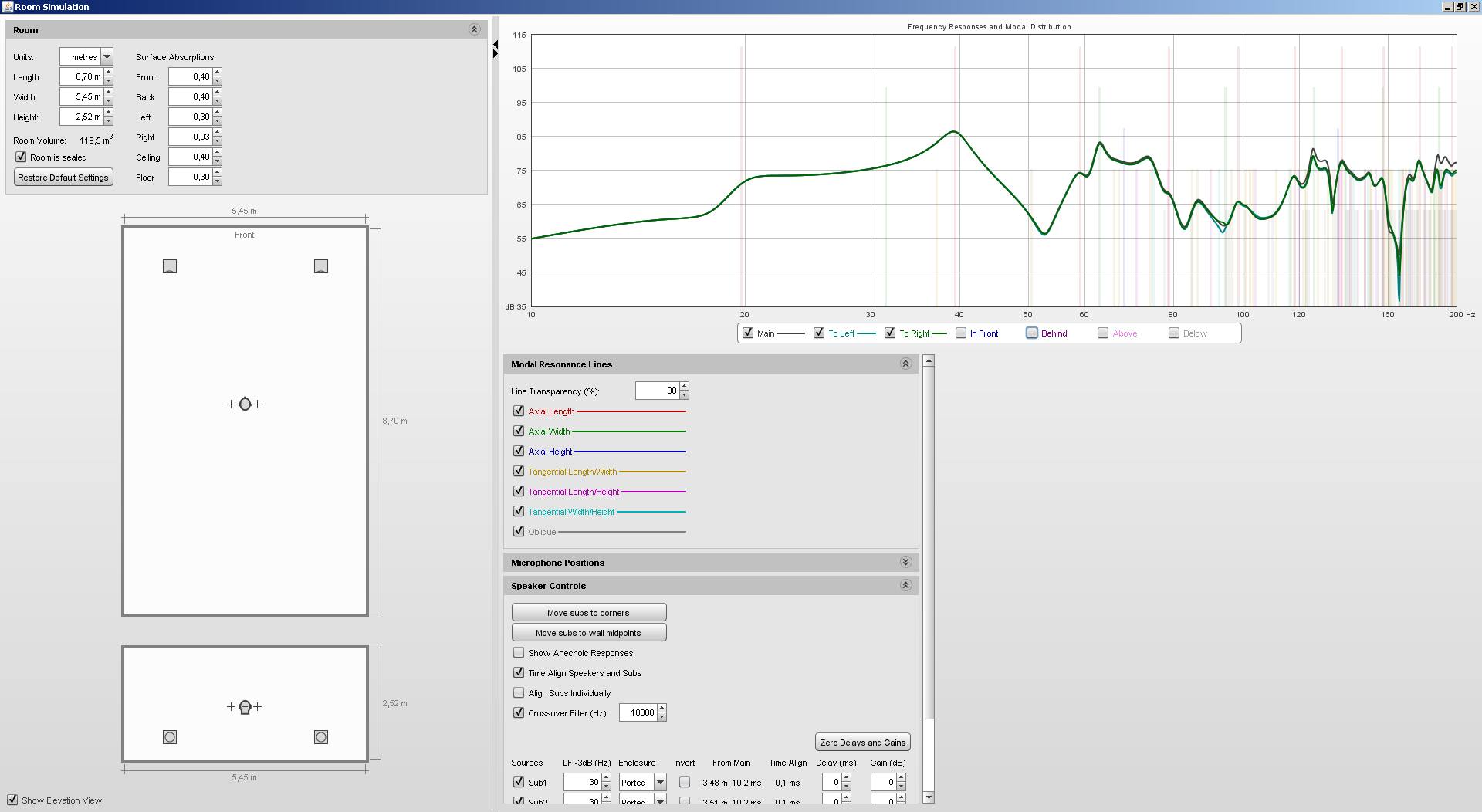
Using a handy program called REW, the influence of resonance frequencies in a closed acoustic space can be simulated.
I put in the inner dimensions of the room: 5.45*8.7*2.5 m. A large part of the ceiling will be occupied by a quadratic acoustic diffuser with the max. depth of 25 cm (12.5 cm on average). Converted to the entire ceiling area, it is 8 cm. That is why I intentionally put in the ceiling height lower by 8 cm. For the initial simulation, we will place the speakers 1 m from the back wall and 1 m from the side walls.
The entire area of the front and back walls is going to be covered by the hybrid diffuser, reflectivity/absorption of which changes in relation to the direction in which acoustic energy reaches it. The same goes for the ceiling and large diffusion areas on the walls. That is why I choose medium reflectivity.
Ears of the listener are in 1.2 m, they sit in the axis of the room and they will be moving from a non-ideal position in the direction of the back wall.
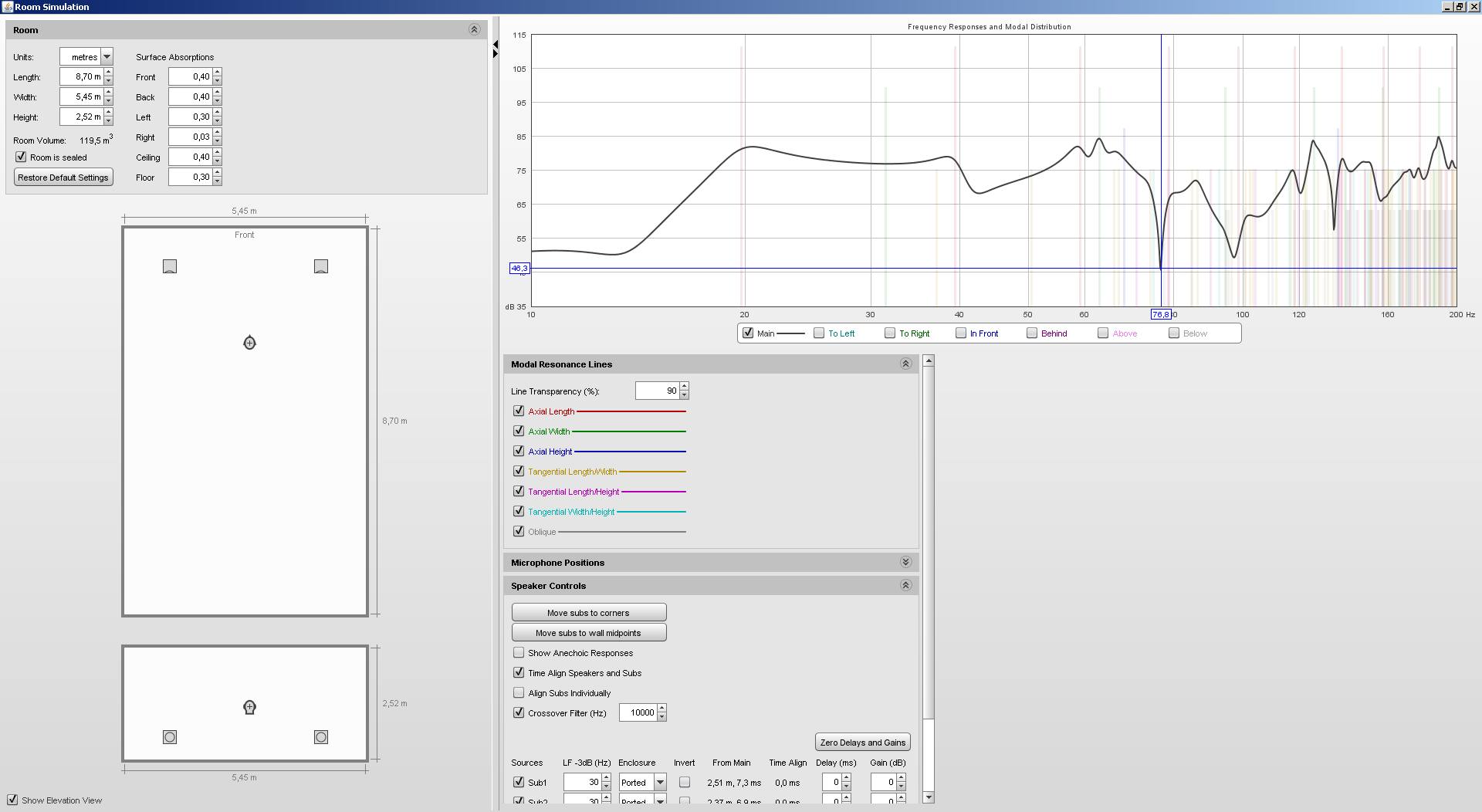
The listener is 2.6 m far from the front wall, we can see a fall on 77 Hz that is starting to fade away in the distance of 3 m.

On 103 Hz, however, another resonance fall becomes apparent. In the distance of 3.6 m from the front wall, the resonance falls equalize.
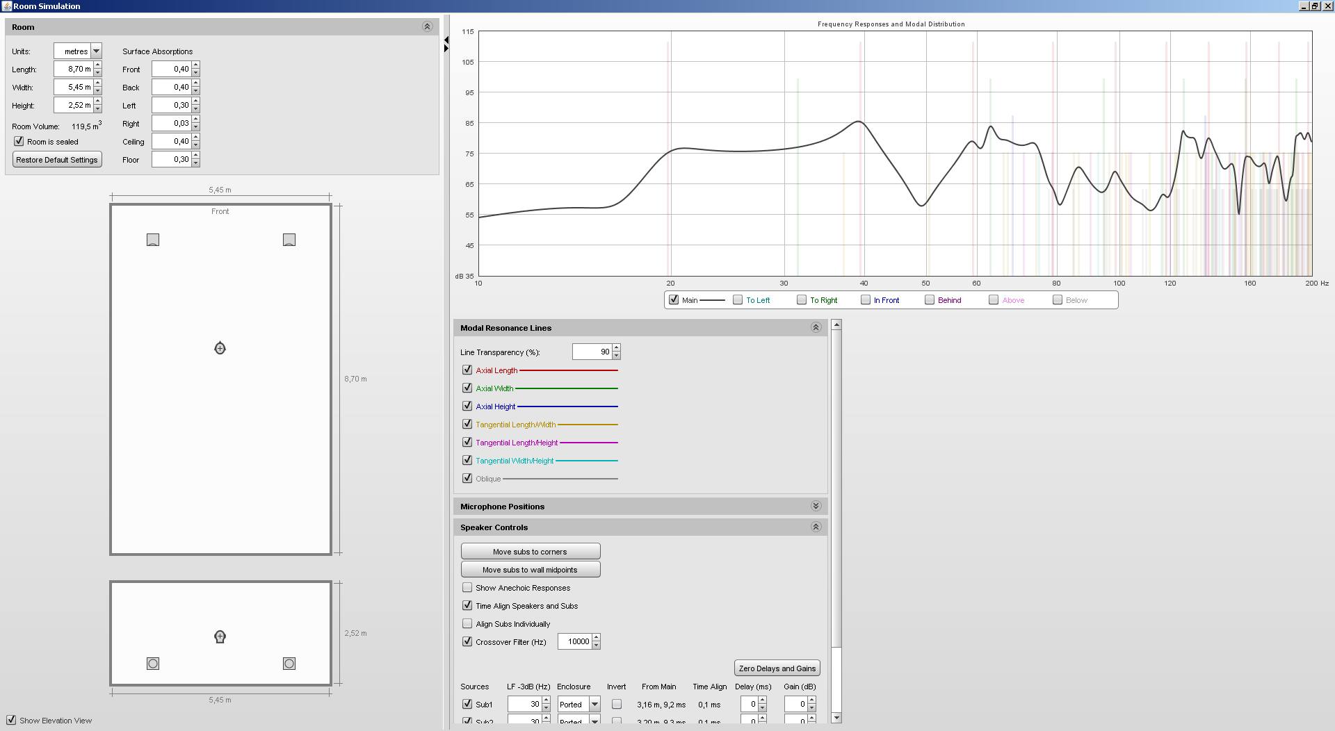
We approximately got to the generally recommended equilateral triangle. Moving the listener to 4 m is not ideal anymore; another fall becomes apparent at 166 Hz.
Here, I highlight the reflections from side walls (turquoise and green) which are most prominent in this position. The two 2*2 m hybrid diffusers placed exactly in the middle of the distance between the speakers and the listener will help with their elimination.
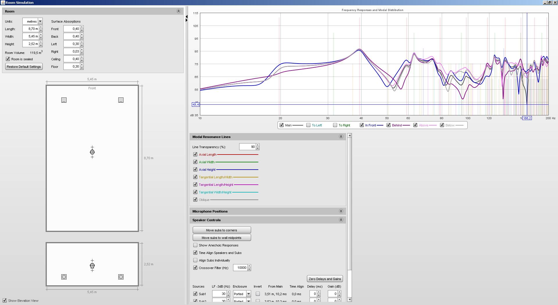
If I highlight other reflections (the front wall is blue, the back purple, ceiling pink, floor grey), we can see that the aforementioned fall at 166 Hz is mostly caused by the side walls.
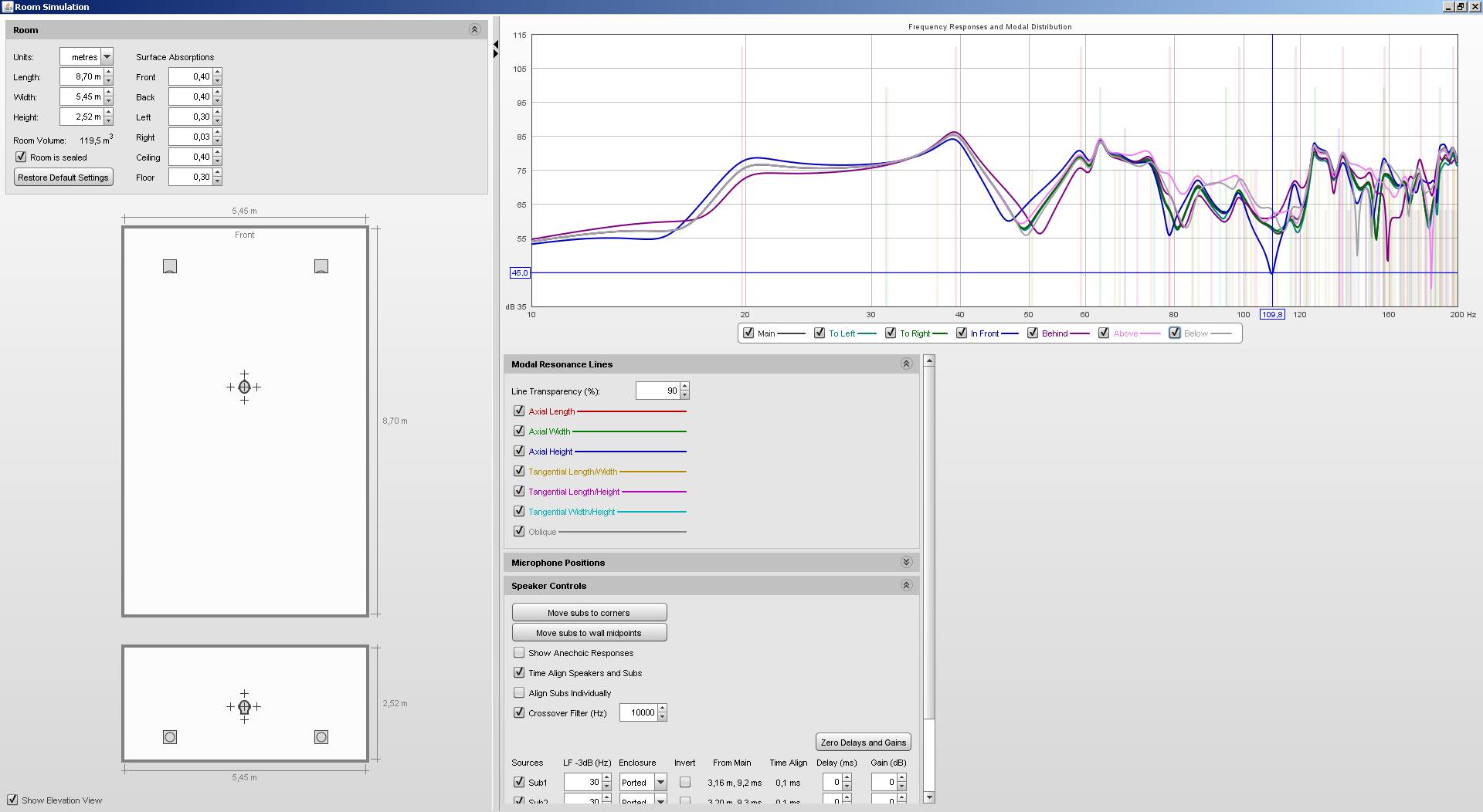
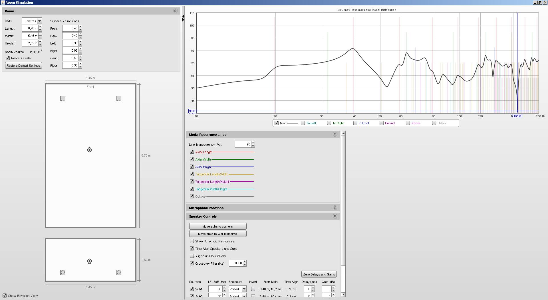
We move again to the most homogenous level of acoustic pressure in the distance of 3.6 m. Highlighting reflections from all walls, we see a fall at 109 Hz (blue) caused by a reflection from the front wall. The whole front wall will be covered by a hybrid acoustic diffuser which is most absorptive in the corners where acoustic energy of low frequencies primarily accumulates. Also, its attenuation coefficient is higher at low frequencies, which is why in reality, the reflection from the front wall will not be as prominent a part of the overall acoustic pressure in the listening spot.
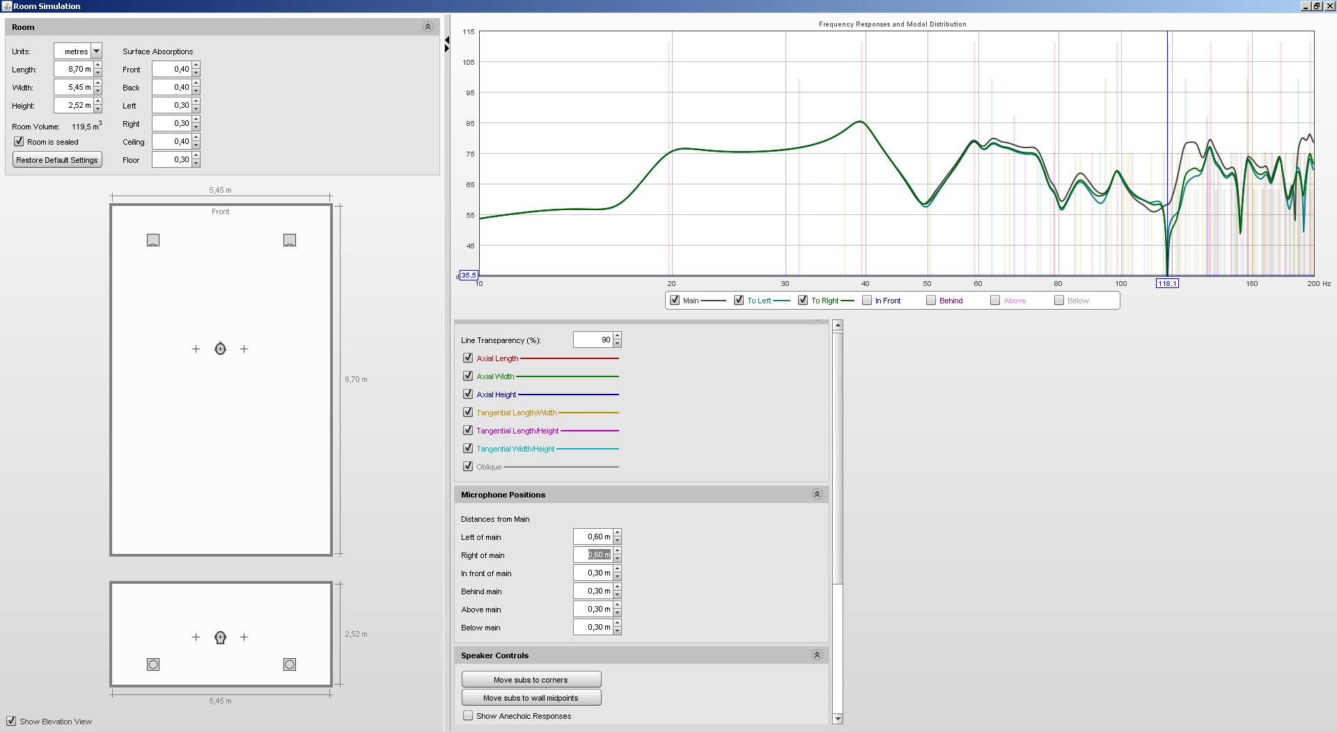
If three people sit in the distance of 3.6 m next to each other with 60cm gaps between them, the listeners on the left and right will hear a fall at 118 Hz (turquoise and green), while the listener in the middle (black) will not hear it.
The simulation can differ from reality due to improperly specified absorption of the sides of the simulated block. Hybrid diffusers change both the absorptive and reflective characteristics in relation to frequency, which is why it is very hard to simulate their influence. Their influence is, however, measurable and hearable, so we have to wait for real measurements.
Ideal Ratios
With modal frequencies in the back of our mind, we extended the original 5.5 x 5.6 x 2.6 m space to an ideal 5.45 x 8.7 x 2.6 m, removing the original partition and building a new one.
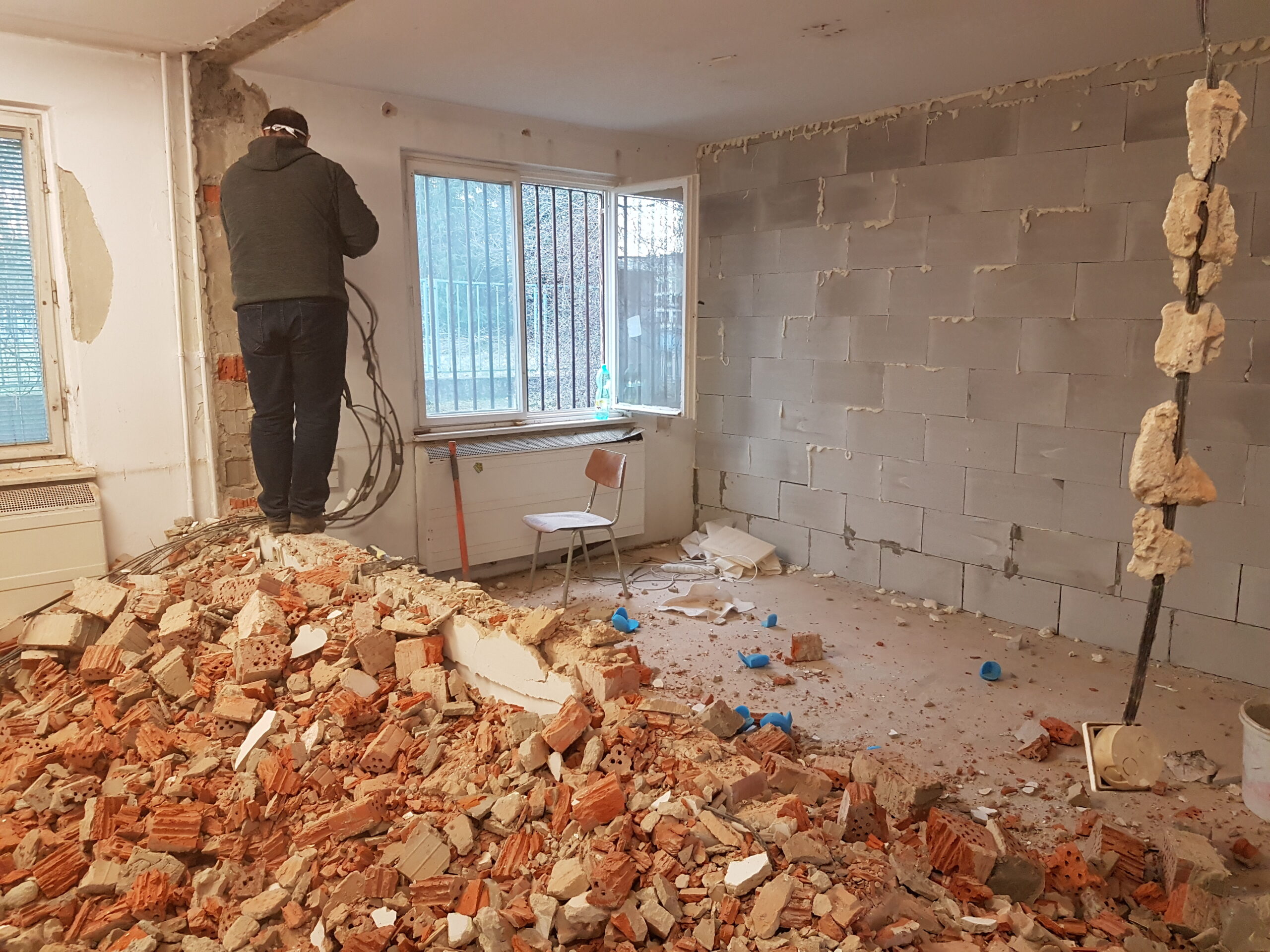
The building skeleton is reinforced concrete, the ceiling and floor concrete—all ideal. Construction materials that are susceptible to vibrations (such as plasterboard or glass) vibrate on certain frequencies and from the point of view of acoustics, they act similarly—as an unwanted mechanical resonator. Our goal is a clear and sound-wise the best space, which is why we wall up the niches between the supporting pillars and the windows. Ventilation will be provided by an automatic heat recovery ventilation unit.
Separate Wiring
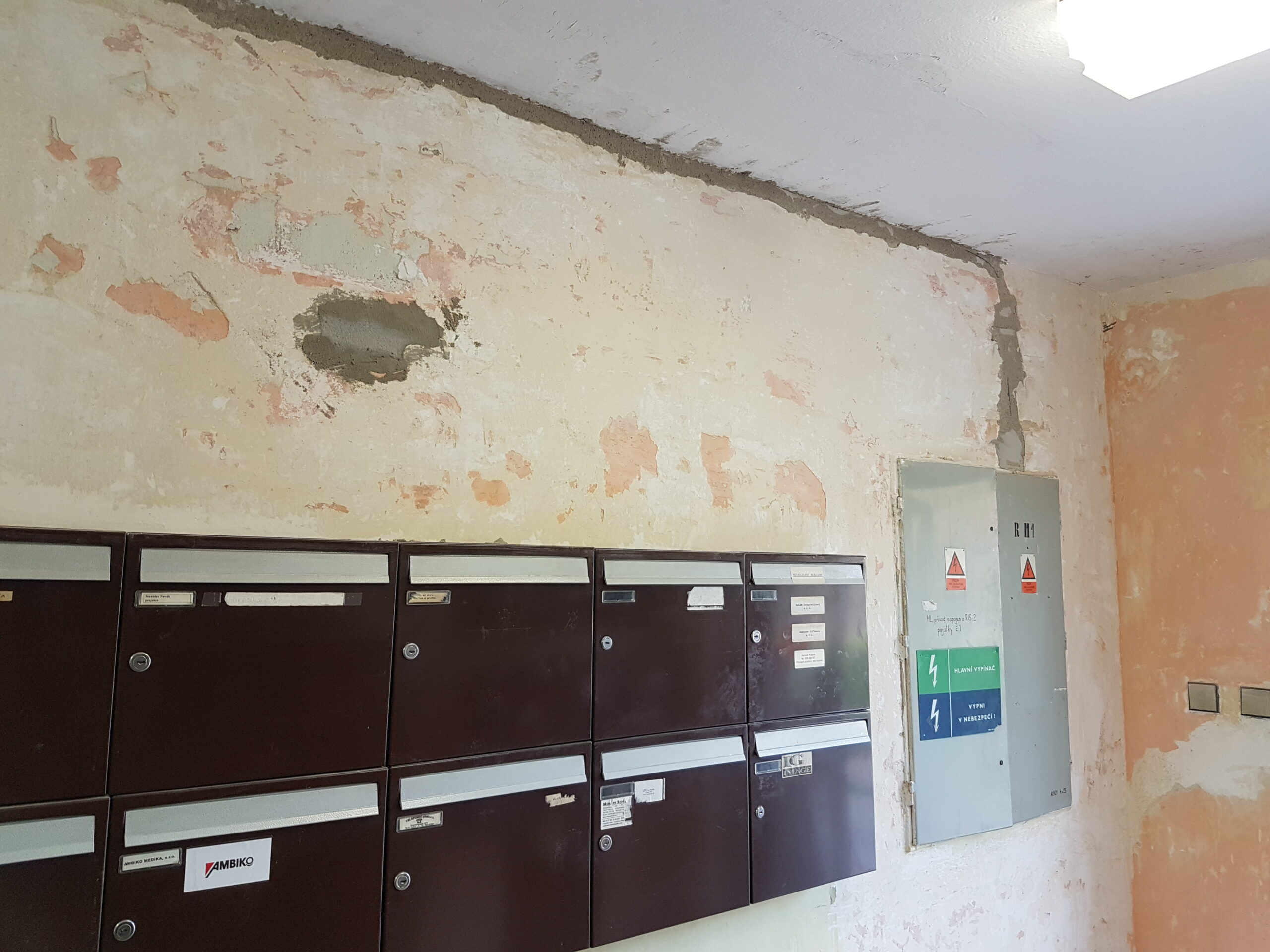
We lay down a new supply leading from the main switchboard using a 5×4 copper conductor. We chose fuses as the securing elements of the individual circuits. We have all three phases coming to our switchboard, so in the future, we are going to be able to choose the one with the least interference to power the audio systems and connect devices with higher electromagnetic emissions, such as LED lighting circuits, to another phase.
Grounding
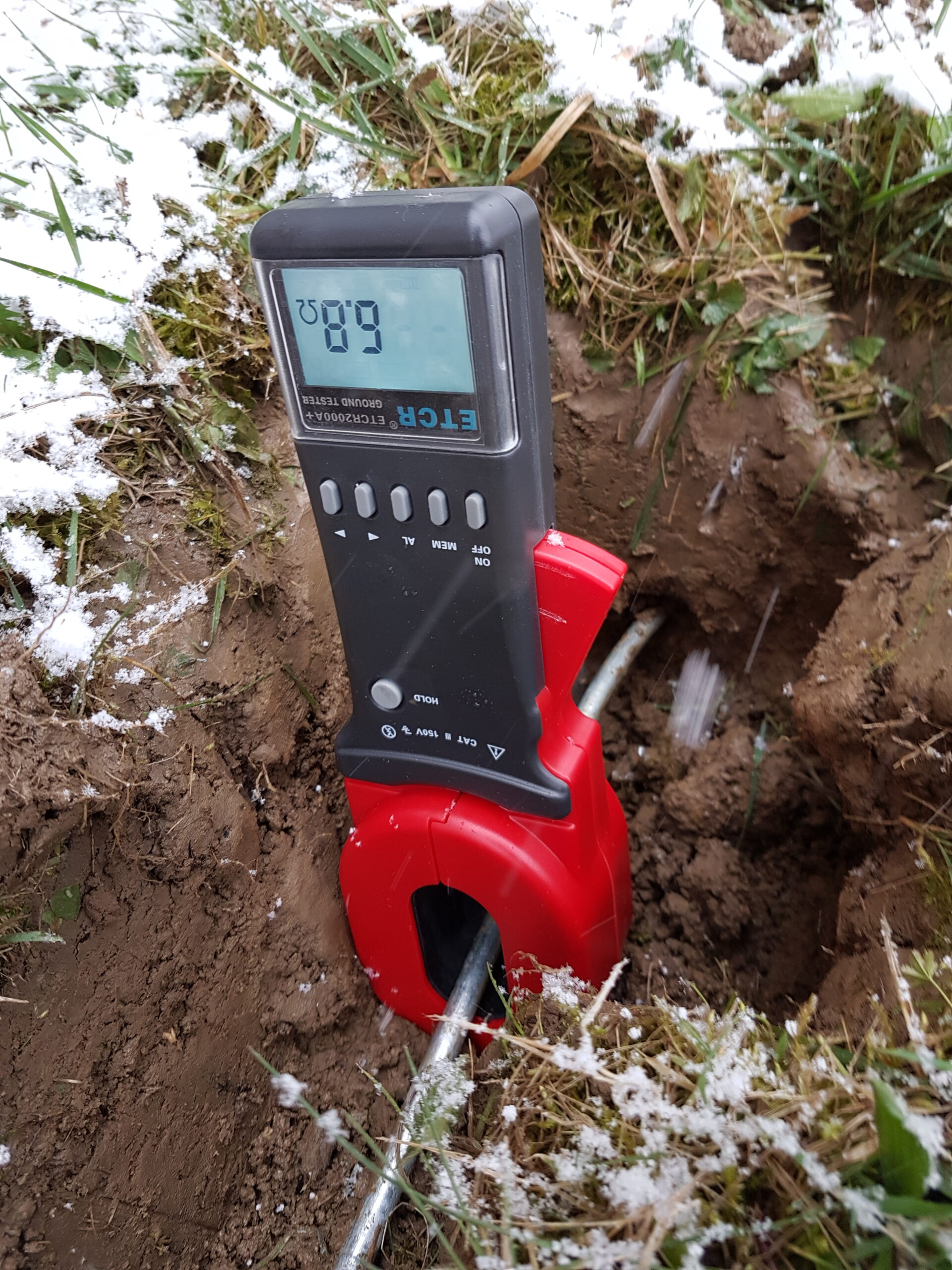
In order to find out the resistivity of the soil behind the building, we used two earthing rods as probes (1 m in the ground, 9 m apart). The resistance between them is 75 Ω, which translates to a very good soil resistivity of 8.3 Ωm. In order to verify the accuracy of the measurement, we put the probe into the depth of 1.5 m and measured 52 Ω, which confirm the initial result. Behind the building, we put down two separate main grounding points, one for each audio system. According to the calculations, we should reach an outstanding grounding resistivity under one ohm with only eleven grounding rods.
Construction Works Finishing
What comes next is leveling the new floor, plastering, laying down the carpet inside and heavy-use grade linoleum in the hall…
Acoustics
As the construction progresses, we prepare the acoustic elements for the room. The next article is going to focus on those.
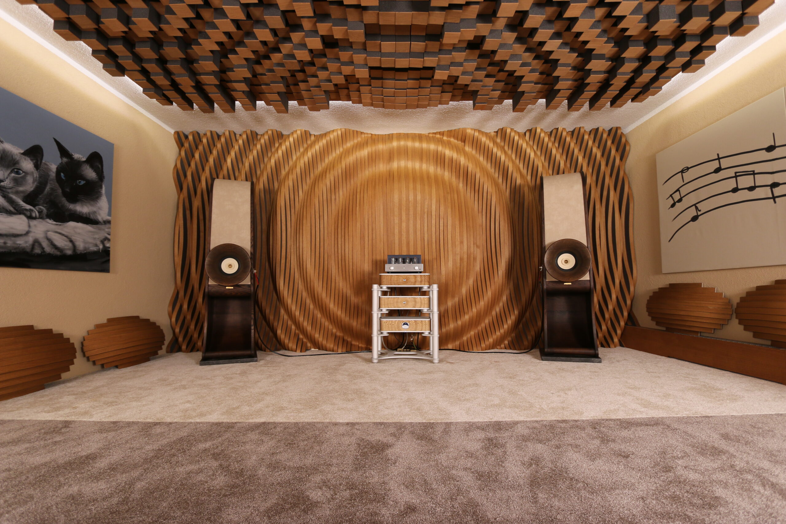
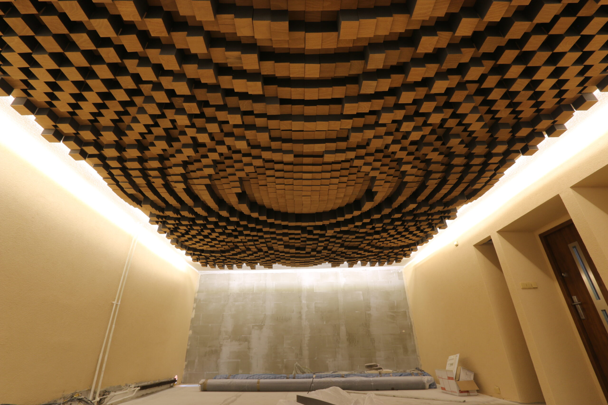
We finished a third step towards a perfect listening space. A hybrid acoustic diffuser now covers almost the entire ceiling. We tried to make a photo of it, but even a wide 10mm lens could not capture it in its entirety.
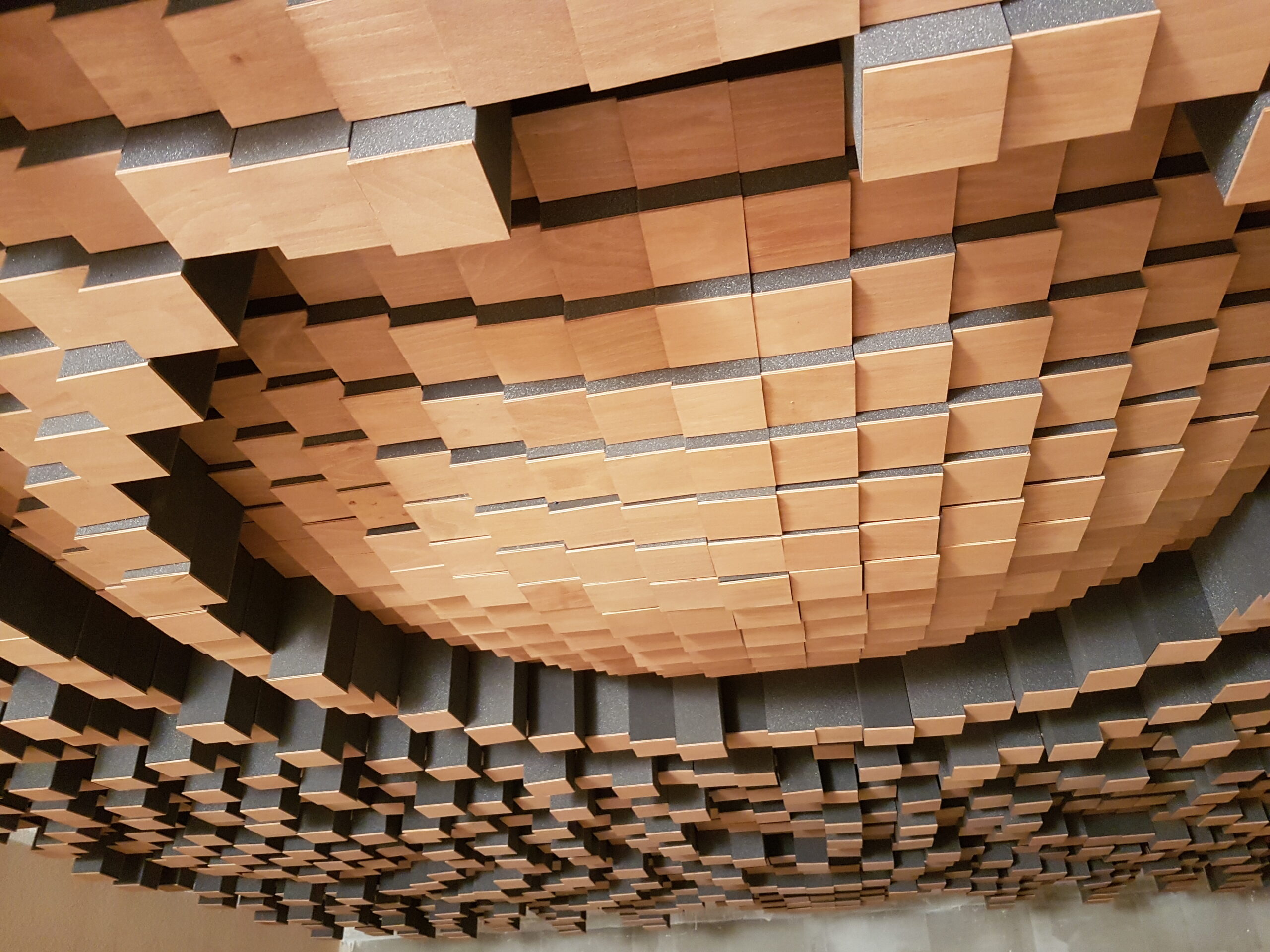
QRD67H – Hybrid acoustic diffuser
This will disperse unwanted acoustic reflection and without absorbing too much acoustic energy inside the space at the same time. There will be more spatiality and perceived openness to the sound. Size: 6.7 x 4.5 m, number of segments: 3015, segment size: 10 x 10 cm.
Along the outline of the ceiling diffuser, there are two separate sections of LED lighting.
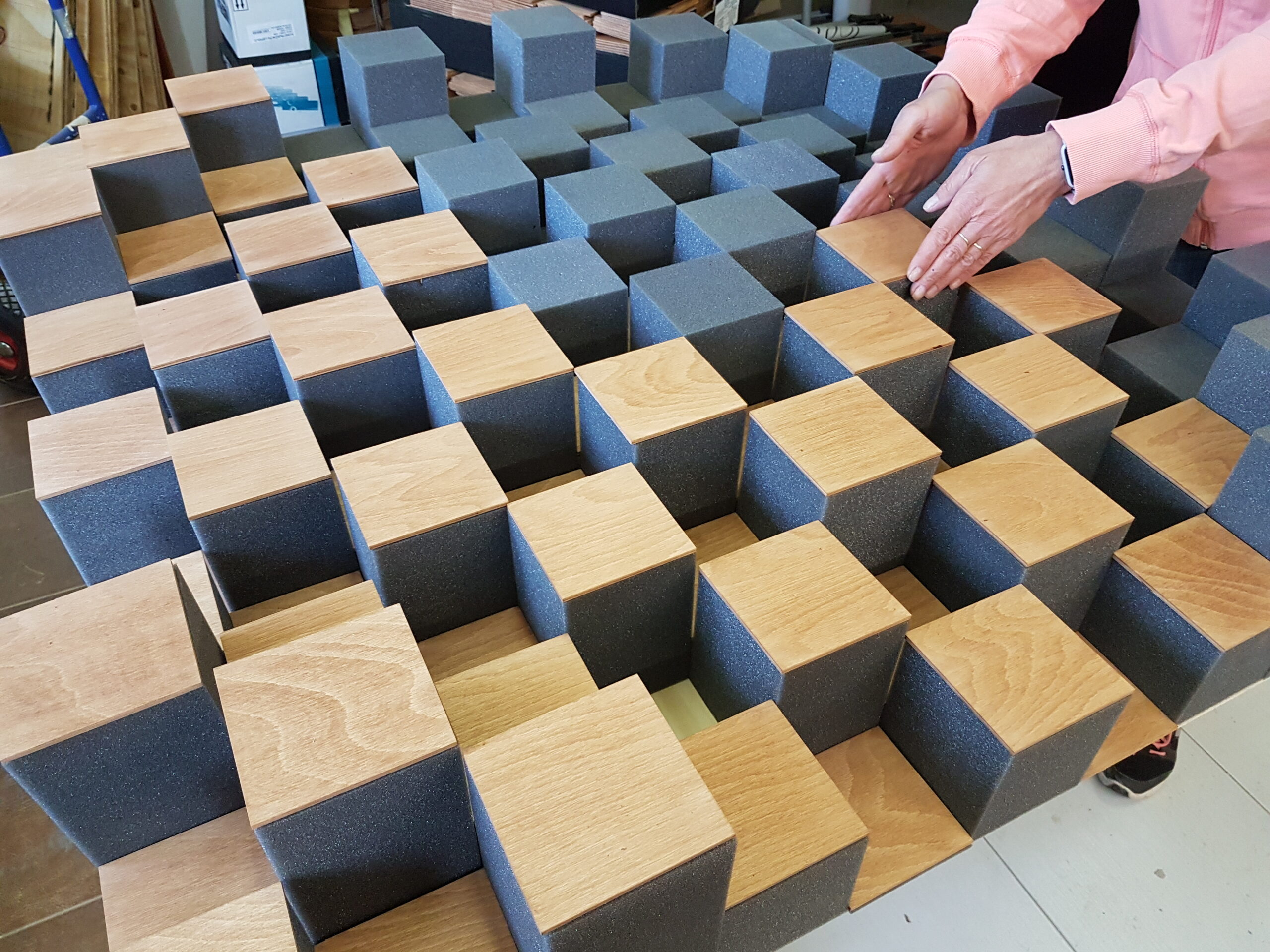
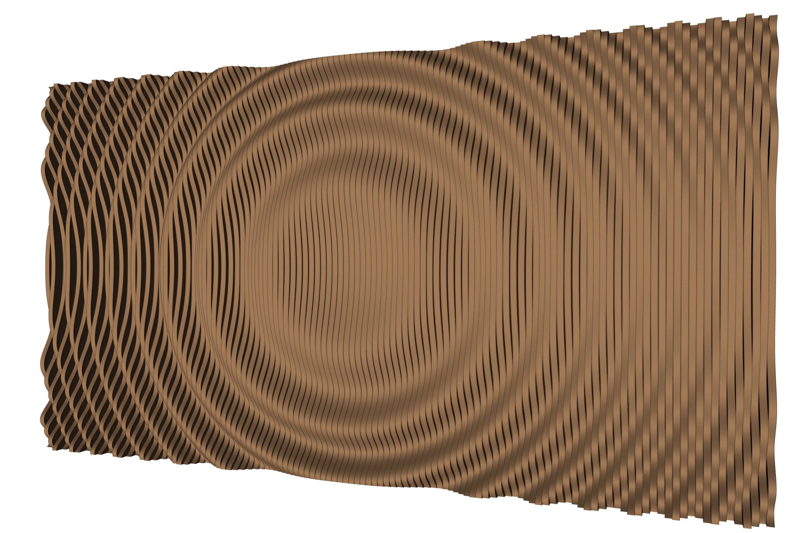
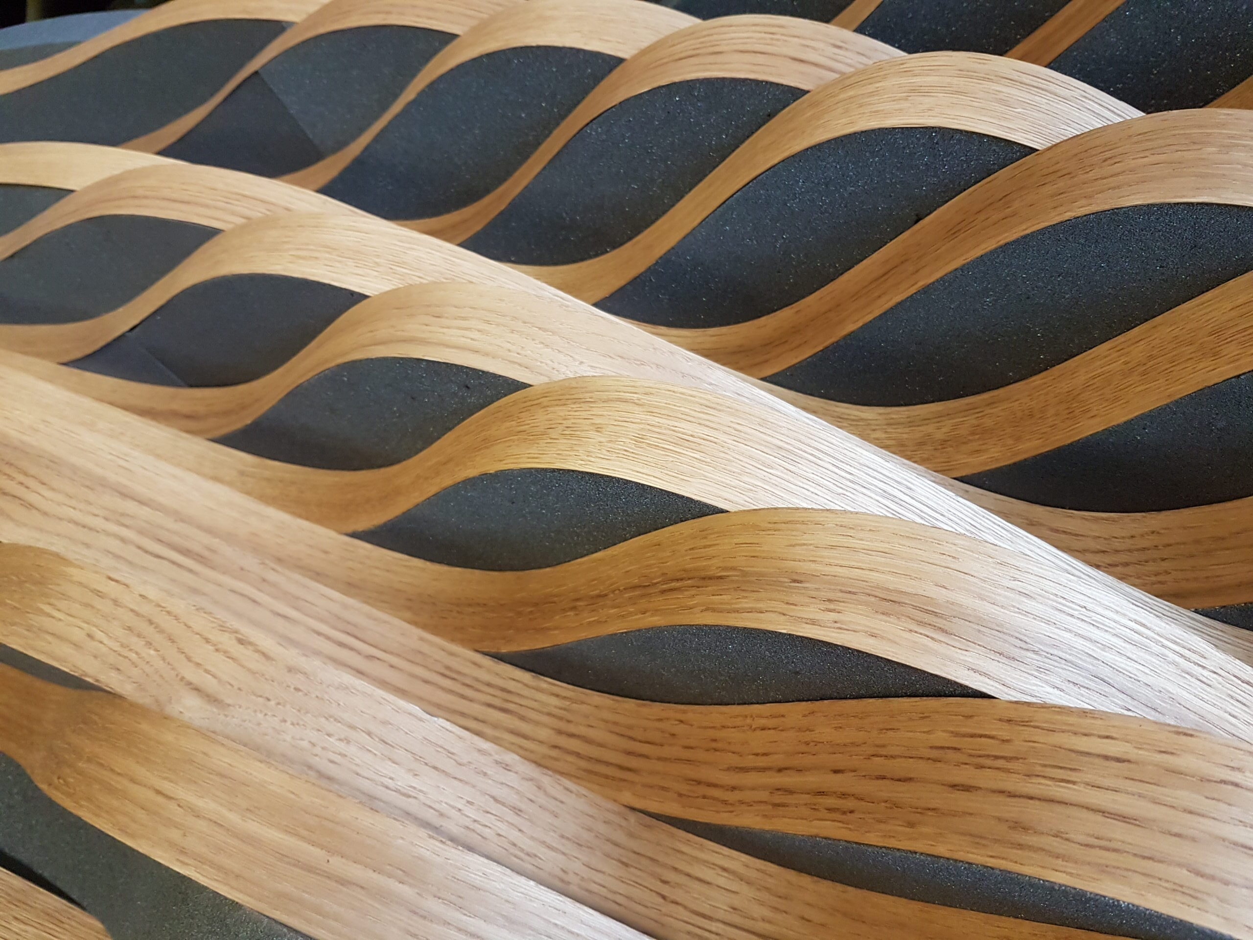
On the front walls of the listening studio, there will be placed two hybrid diffusers we are currently preparing in our workshop. A detail is shown below. Segments made from acoustic foam are covered with a thin layer of real oak wood treated with natural oil.
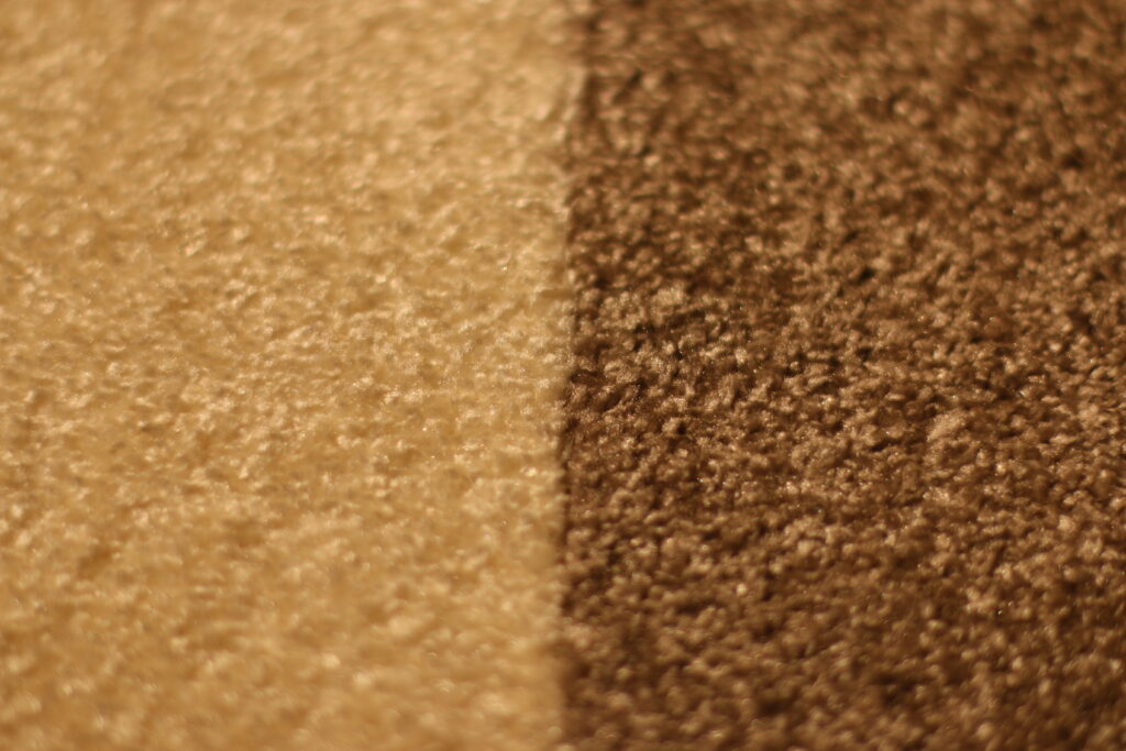
Taking in mind the acoustic parameters, for the floor, we chose a high quality carpet with high pile (11 mm) made of polypropylene fibres.
Part 2 of this post is going to bring a look at acoustic measurements following the individual steps of acoustic treatment, including subjective evaluation of the sound.
Our Goals
- Optimising the ratio of the listening space walls—optimising modal resonance frequencies in a closed space (applicable to up to cca. 200 Hz)
- Optimising reverberation times on low frequencies
- Ideal ratio of acoustically absorbing and diffusing elements
- Ideally positioned speakers and the listening spot
- A standalone grounding point and power source completely galvanically separated from the power grid
- Electromagnetic shielding underneath the audio system (larger signal/noise distance)
- Video projection
- Two listening systems
- The listening space is in a quiet location, aside from the main road, yet accessible with its own parking lot. The ratio of wall sizes in the room is not ideal though, so construction works are ahead of us. We are going to enlarge the current space, brick up niches between the supporting pillars of the building and acoustically seal up the windows. Further, we are going to lay down our own wiring to our switchboard, with standalone circuits for each audio system, lighting and the ventilation system.
- Acoustic treatment:
- Ceiling QRD Hybrid Diffuser 6.7*4.5 m, 25 cm in depth
- Acoustically absorptive carpet
- System 1
- Hybrid Diffuser 5.45*2.6 m, 20 cm depth
- Left Hybrid Diffuser 2*2 m (circle pattern)
- Right inverse Hybrid Diffuser 2*2 m (circle pattern)
- Other acoustic treatment is going to be decided upon on the basis of measurements and subjective tests.
- System 2
- Inverse Hybrid diffuser 5.45*2.6 m, 20 cm depth
- Left Hybrid Diffuser 2*2 m (circle pattern)
- Right inverse Hybrid Diffuser 2*2 m (circle pattern)
- Other acoustic treatment is going to be decided upon on the basis of measurements and subjective tests.
- Audio system power supply
- Each system will have its own power circuit, complete galvanic separation and a standalone grounding point.
- Shielding under each system + preparation for taking electrical measurements
- Preliminary simulation of modal frequencies
Using a handy program called REW, the influence of resonance frequencies in a closed acoustic space can be simulated.
I put in the inner dimensions of the room: 5.45*8.7*2.5 m. A large part of the ceiling will be occupied by a quadratic acoustic diffuser with the max. depth of 25 cm (12.5 cm on average). Converted to the entire ceiling area, it is 8 cm. That is why I intentionally put in the ceiling height lower by 8 cm. For the initial simulation, we will place the speakers 1 m from the back wall and 1 m from the side walls.
The entire area of the front and back walls is going to be covered by the hybrid diffuser, reflectivity/absorption of which changes in relation to the direction in which acoustic energy reaches it. The same goes for the ceiling and large diffusion areas on the walls. That is why I choose medium reflectivity.
Ears of the listener are in 1.2 m, they sit in the axis of the room and they will be moving from a non-ideal position in the direction of the back wall.
The listener is 2.6 m far from the front wall, we can see a fall on 77 Hz that is starting to fade away in the distance of 3 m.
On 103 Hz, however, another resonance fall becomes apparent. In the distance of 3.6 m from the front wall, the resonance falls equalize.
We approximately got to the generally recommended equilateral triangle. Moving the listener to 4 m is not ideal anymore; another fall becomes apparent at 166 Hz.
Here, I highlight the reflections from side walls (turquoise and green) which are most prominent in this position. The two 2*2 m hybrid diffusers placed exactly in the middle of the distance between the speakers and the listener will help with their elimination.
If I highlight other reflections (the front wall is blue, the back purple, ceiling pink, floor grey), we can see that the aforementioned fall at 166 Hz is mostly caused by the side walls.
We move again to the most homogenous level of acoustic pressure in the distance of 3.6 m. Highlighting reflections from all walls, we see a fall at 109 Hz (blue) caused by a reflection from the front wall. The whole front wall will be covered by a hybrid acoustic diffuser which is most absorptive in the corners where acoustic energy of low frequencies primarily accumulates. Also, its attenuation coefficient is higher at low frequencies, which is why in reality, the reflection from the front wall will not be as prominent a part of the overall acoustic pressure in the listening spot.
If three people sit in the distance of 3.6 m next to each other with 60cm gaps between them, the listeners on the left and right will hear a fall at 118 Hz (turquoise and green), while the listener in the middle (black) will not hear it.
The simulation can differ from reality due to improperly specified absorption of the sides of the simulated block. Hybrid diffusers change both the absorptive and reflective characteristics in relation to frequency, which is why it is very hard to simulate their influence. Their influence is, however, measurable and hearable, so we have to wait for real measurements.
Ideal Ratios
With modal frequencies in the back of our mind, we extended the original 5.5 x 5.6 x 2.6 m space to an ideal 5.45 x 8.7 x 2.6 m, removing the original partition and building a new one.
The building skeleton is reinforced concrete, the ceiling and floor concrete—all ideal. Construction materials that are susceptible to vibrations (such as plasterboard or glass) vibrate on certain frequencies and from the point of view of acoustics, they act similarly—as an unwanted mechanical resonator. Our goal is a clear and sound-wise the best space, which is why we wall up the niches between the supporting pillars and the windows. Ventilation will be provided by an automatic heat recovery ventilation unit.
Separate Wiring
We lay down a new supply leading from the main switchboard using a 5×4 copper conductor. We chose fuses as the securing elements of the individual circuits. We have all three phases coming to our switchboard, so in the future, we are going to be able to choose the one with the least interference to power the audio systems and connect devices with higher electromagnetic emissions, such as LED lighting circuits, to another phase.
Grounding
In order to find out the resistivity of the soil behind the building, we used two earthing rods as probes (1 m in the ground, 9 m apart). The resistance between them is 75 Ω, which translates to a very good soil resistivity of 8.3 Ωm. In order to verify the accuracy of the measurement, we put the probe into the depth of 1.5 m and measured 52 Ω, which confirm the initial result. Behind the building, we put down two separate main grounding points, one for each audio system. According to the calculations, we should reach an outstanding grounding resistivity under one ohm with only eleven grounding rods.
Construction Works Finishing
What comes next is leveling the new floor, plastering, laying down the carpet inside and heavy-use grade linoleum in the hall…
Acoustics
As the construction progresses, we prepare the acoustic elements for the room. The next article is going to focus on those.
We finished a third step towards a perfect listening space. A hybrid acoustic diffuser now covers almost the entire ceiling. We tried to make a photo of it, but even a wide 10mm lens could not capture it in its entirety.
QRD67H – Hybrid acoustic diffuser
This will disperse unwanted acoustic reflection and without absorbing too much acoustic energy inside the space at the same time. There will be more spatiality and perceived openness to the sound. Size: 6.7 x 4.5 m, number of segments: 3015, segment size: 10 x 10 cm.
Along the outline of the ceiling diffuser, there are two separate sections of LED lighting.
On the front walls of the listening studio, there will be placed two hybrid diffusers we are currently preparing in our workshop. A detail is shown below. Segments made from acoustic foam are covered with a thin layer of real oak wood treated with natural oil.
Taking in mind the acoustic parameters, for the floor, we chose a high quality carpet with high pile (11 mm) made of polypropylene fibres.
Part 2 of this post is going to bring a look at acoustic measurements following the individual steps of acoustic treatment, including subjective evaluation of the sound.
