Analog audio signal transmission via optical fibre
Intro
Though contemporary individual SOTA audio sources (DACs) and preamplifiers and power amplifiers are at the parameters level that any improvements remain inaudible, after the components are interconnected via shielded or coaxial cables, it is not unusual that S/N parameters are degraded of 40 – 50 dB due to ground loops, especially in case of unbalanced single ended connection. One of the worst cases is a PC in class I feeding DAC in class I via non-isolated USB, and then the analog signal going to class I preamplifier or integrated amplifier. Buzz, clicks, drop-outs are not unusual, however even less evident degradation may occur as well.
USB link between the PC and the DAC should always be isolated and the isolated adapter should have the lowest possible stray capacitance. The other solution is a Toslink cable and isolated USB/SPDIF converter connected to the PC.
Sometimes we also need to have analog link signal with galvanic isolation. Signal transformers are a possible solution, but they may suffer from elevated LF distortion at higher signal level and also their stray capacitance is not negligible, allowing HF interference currents to flow in the circuit. The complete isolation solution is an optic fibre, which totally isolates signal source from the receiving circuit.
From 1980 to 2000 I designed and produced a number of fibre optic analog transmission systems that have been used in high voltage laboratories and HV circuit breakers testing plants. I thought it might be fun to try a principle of those systems to transfer audio signal.
Optical transmitter diodes are non-linear devices and their optical power is a subject of aging. Light power loss also depend on fibre length and precision of connectors used. Thus, it is impossible to get highly linear and repeatable parameters from direct analog transmission from transmitter diode – receiving diode couple. The solution is to use pulse width modulation (like class D) or pulse frequency modulation. Then, the system is immune to fibre length change or transmitter aging, if we operate within specified limits.
For the experiment with audio signal, I used Teledyne Philbrick 4705 VFC (voltage-to-frequency) converter (1974!). It transfers 0 - 10V input signal into train of impulses with frequency 0 – 1MHz. We may shift the base Fo frequency (for 0V input) and get the ability to transfer AC signals up to +/-5V. I am using base frequency Fo = 350kHz and transfer ratio 100kHz/V. For +/-2.8Vp input (2Vrms) we get range of transmission frequencies 70kHz – 630kHz. Signal from the VFC is easily coupled to the fiber optic link Broadcom HFBR1521 – HFBR2521. Output of the receiver module HFBR2521 triggers a monostable circuit with fixed output impulse width. Average value of the monostable circuit output is proportional to VFC analog input voltage. So the demodulation of the frequency modulated impulse train may be done with a simple passive low-pass filter.
VFC optical transmission sample
This is the schematics:

and the functional sample looks like this:

This is the impulse train output monitored on the optical fibre end:

Some measurements
Let's measure some audio parameters of the complete optical analog transmission link.
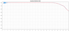
Frequency response is defined by the 2RC low-pass filter used:

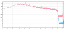
Distortion at -6dBFS is about 0.7%, (edit - can be and was improved easily) with S/N = 80dB (similar to best tape recorders). There is no elevated high-frequency noise floor.

Noise floor

Square wave response is almost ideal:

Sine wave record:

Listening test
I have prepared a listening test, original 96/24 file and the same file recorded via the VFC optical transmission system described in this thread. The files may be downloaded from:
 drive.google.com
If you are interested, please feel free to download the files and share your foobar ABX report with us.
Below please find what the Deltawave says about the files:


____________________________________________________________________________________________________________________________________
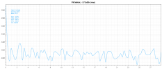
P.S: After playing with the circuit a bit, I assume this is the limit with this VFC:

Intro
Though contemporary individual SOTA audio sources (DACs) and preamplifiers and power amplifiers are at the parameters level that any improvements remain inaudible, after the components are interconnected via shielded or coaxial cables, it is not unusual that S/N parameters are degraded of 40 – 50 dB due to ground loops, especially in case of unbalanced single ended connection. One of the worst cases is a PC in class I feeding DAC in class I via non-isolated USB, and then the analog signal going to class I preamplifier or integrated amplifier. Buzz, clicks, drop-outs are not unusual, however even less evident degradation may occur as well.
USB link between the PC and the DAC should always be isolated and the isolated adapter should have the lowest possible stray capacitance. The other solution is a Toslink cable and isolated USB/SPDIF converter connected to the PC.
Sometimes we also need to have analog link signal with galvanic isolation. Signal transformers are a possible solution, but they may suffer from elevated LF distortion at higher signal level and also their stray capacitance is not negligible, allowing HF interference currents to flow in the circuit. The complete isolation solution is an optic fibre, which totally isolates signal source from the receiving circuit.
From 1980 to 2000 I designed and produced a number of fibre optic analog transmission systems that have been used in high voltage laboratories and HV circuit breakers testing plants. I thought it might be fun to try a principle of those systems to transfer audio signal.
Optical transmitter diodes are non-linear devices and their optical power is a subject of aging. Light power loss also depend on fibre length and precision of connectors used. Thus, it is impossible to get highly linear and repeatable parameters from direct analog transmission from transmitter diode – receiving diode couple. The solution is to use pulse width modulation (like class D) or pulse frequency modulation. Then, the system is immune to fibre length change or transmitter aging, if we operate within specified limits.
For the experiment with audio signal, I used Teledyne Philbrick 4705 VFC (voltage-to-frequency) converter (1974!). It transfers 0 - 10V input signal into train of impulses with frequency 0 – 1MHz. We may shift the base Fo frequency (for 0V input) and get the ability to transfer AC signals up to +/-5V. I am using base frequency Fo = 350kHz and transfer ratio 100kHz/V. For +/-2.8Vp input (2Vrms) we get range of transmission frequencies 70kHz – 630kHz. Signal from the VFC is easily coupled to the fiber optic link Broadcom HFBR1521 – HFBR2521. Output of the receiver module HFBR2521 triggers a monostable circuit with fixed output impulse width. Average value of the monostable circuit output is proportional to VFC analog input voltage. So the demodulation of the frequency modulated impulse train may be done with a simple passive low-pass filter.
VFC optical transmission sample
This is the schematics:
and the functional sample looks like this:
This is the impulse train output monitored on the optical fibre end:
Some measurements
Let's measure some audio parameters of the complete optical analog transmission link.
Frequency response is defined by the 2RC low-pass filter used:
Distortion at -6dBFS is about 0.7%, (edit - can be and was improved easily) with S/N = 80dB (similar to best tape recorders). There is no elevated high-frequency noise floor.
Noise floor
Square wave response is almost ideal:
Sine wave record:
Listening test
I have prepared a listening test, original 96/24 file and the same file recorded via the VFC optical transmission system described in this thread. The files may be downloaded from:
VFC_test.zip
 drive.google.com
If you are interested, please feel free to download the files and share your foobar ABX report with us.
Below please find what the Deltawave says about the files:


____________________________________________________________________________________________________________________________________
P.S: After playing with the circuit a bit, I assume this is the limit with this VFC:
Last edited:

