
My 60-year interest in audio as a hobby is not based on seeking audio nirvana or the perfect sound, but rather a fascination with the incredibly wide range of electronics technologies and speaker designs that can reproduce music in a satisfying and often quite realistic manner. Although the proponents of various approaches and methods can often get into serious "food-fights," I have enjoyed the results of several approaches to high-fidelity audio.
While writing another post in an amplifiers evolution thread, I drifted off into a discussion of amplifier wiring methods and DIY projects of various levels. So I transferred that portion here and started this thread to discuss some of the myriad aspects of amplifier design, not from the aspect of differences in the electronic circuits, but related to the physical and mechanical aspects of assembly and interconnection of the internal electronic components that make up circuits. I will likely return here occasionally with a new andlg on the subject.
Disclaimer: I am not an electronics engineer, or even an electronics technician. However, I can solder, use a multimeter and oscilloscope, do a bit of crude metalwork, and have a very basic understanding of electronic circuits.
1960 to 1990 was a fascinating period of rapid audio amplifier design evolution that went from from point-to-point wired tube amps to "through-hole" printed circuit boards to surface-mount technology. Most consumer electronics amplifiers now use surface-mount designs, but in the audio enthusiast community, there are still many vacuum tube amplifiers being made that use - and often swear by - point-to-point wiring. Through-hole PCB designs are also still used for both tube and SS amplifiers.
In that other thread, I suggested that people check out a website - Vintage Audio Addict. It is dedicated to repairing and restoring 1960's-1980's vintage audio gear. The extensive collection of projects at Vintage Audio Addict includes the restoration of a Pioneer SX-1980, and the website shows what is inside this and other classic components. One fascinating aspect of his presentation style is the opportunity to observe the evolution of audio circuits from the first one - point-to-point wiring - to including one or more simple printed circuit boards, and then moving on to more modern-style complex, high component density PCBs. If you look at some of his projects, you can also see some of the different circuit implementation "styles" used by various manufacturers. The website is not a step-by-step how-to, but rather is shows a few interesting points for each project.
If you not an audiophile or audio hobbyist when you first arrive at ASR, and if you end up liking this place and hang around for a while, you are more than a typical consumer electronics customer and user. And if you don't know much about electronics and would like to learn a bit, you can hang out at ASR and follow some of the links that are posted in many threads. There are some great opportunities here to begin to learn a bit about what is on the inside of audio components.
If you decide to try a DIY audio project, I see three levels of amplifier-assembly:
I will be assembling a Ghent/ICEpower kit, the version with a bit of soldering, and also a "snap-Together" RaspberryPi/HifiBerry or similar kit in a couple of months. Expert DIY'ers make fun of those kits, and I agree that they do not contstitute "building" an amplifier or computer/DAC - but they can certainly save you a lot of money.
And don't hesitate to ask the experts here (not me) about what you are looking at in the interior of amplifiers and other audio components, because learning comes from asking questions - not coming from a perspective of cluelessness and then telling the experts what they should do.
Let's start this with three basic circuit styles. Point-to-point, which is still popular in modern vacuum tube amplifiers

----------------------------
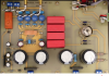
Below is what appears to me to be a (1980's) single-layer "through-hole PCB - soldering on the bottom

--------------------
And here is a modern surface-mount PCB - complex layout, likely multi-layer construction, tiny solder connections, and very difficult to hand-solder chip/component replacements. This particular board is the main board of a Teac A-H01 - a DAC/25wpcAmp. I bought one of these in 2012, and brought it with me when I moved to Panama, and it died six years later - it simply stopped working. My local electronics tech said that it needed a new main board, and Teac did not respond to my email inquiry - so I threw it in the trash. Experts, please correct me if I am wrong, but many modern amplifiers/DACs use complex boards like this that are not typically repairable in the field. I assume that "good" amplifier manufacturers replace boards for warranty repairs, and possibly return their more expensive boards to the PCB manufacturer/assembly people for repair when possible. I also assume that repair of older complex amplifier PCB's is often prohibitively expensive - if not impossible.

----------------------------------------
Last, here is a variation of the "through-hole" PCB - what looks to me to be a double layer PCB. This is from a USB DAC + tube/SS hybrid amplifier (25wpc@8Ω) that is available from Canada's Musical Paradise for $188 - a real bargain if it's as good as its owners report.

While writing another post in an amplifiers evolution thread, I drifted off into a discussion of amplifier wiring methods and DIY projects of various levels. So I transferred that portion here and started this thread to discuss some of the myriad aspects of amplifier design, not from the aspect of differences in the electronic circuits, but related to the physical and mechanical aspects of assembly and interconnection of the internal electronic components that make up circuits. I will likely return here occasionally with a new andlg on the subject.
Disclaimer: I am not an electronics engineer, or even an electronics technician. However, I can solder, use a multimeter and oscilloscope, do a bit of crude metalwork, and have a very basic understanding of electronic circuits.
1960 to 1990 was a fascinating period of rapid audio amplifier design evolution that went from from point-to-point wired tube amps to "through-hole" printed circuit boards to surface-mount technology. Most consumer electronics amplifiers now use surface-mount designs, but in the audio enthusiast community, there are still many vacuum tube amplifiers being made that use - and often swear by - point-to-point wiring. Through-hole PCB designs are also still used for both tube and SS amplifiers.
In that other thread, I suggested that people check out a website - Vintage Audio Addict. It is dedicated to repairing and restoring 1960's-1980's vintage audio gear. The extensive collection of projects at Vintage Audio Addict includes the restoration of a Pioneer SX-1980, and the website shows what is inside this and other classic components. One fascinating aspect of his presentation style is the opportunity to observe the evolution of audio circuits from the first one - point-to-point wiring - to including one or more simple printed circuit boards, and then moving on to more modern-style complex, high component density PCBs. If you look at some of his projects, you can also see some of the different circuit implementation "styles" used by various manufacturers. The website is not a step-by-step how-to, but rather is shows a few interesting points for each project.
If you not an audiophile or audio hobbyist when you first arrive at ASR, and if you end up liking this place and hang around for a while, you are more than a typical consumer electronics customer and user. And if you don't know much about electronics and would like to learn a bit, you can hang out at ASR and follow some of the links that are posted in many threads. There are some great opportunities here to begin to learn a bit about what is on the inside of audio components.
If you decide to try a DIY audio project, I see three levels of amplifier-assembly:
- From scratch or "barebone" kits (requires substantial skill and knowledge)
- Component and/or module kits with anywhere from a little to a lot of soldering. Soldering point-to-point circuits can be complex and difficult unless you have the desire and patience to learn the skills. Positioning and soldering components on "through-hole" printed circuit boards can be easier than P-to-P wiring.
- Easiest of all are the modern, ultra simple "screw together and snap together" kits such as like the Ghent/ICEPower or Hypex amplifier kits, or RaspberryPi+HiFiBerry computer/DAC kits.
I will be assembling a Ghent/ICEpower kit, the version with a bit of soldering, and also a "snap-Together" RaspberryPi/HifiBerry or similar kit in a couple of months. Expert DIY'ers make fun of those kits, and I agree that they do not contstitute "building" an amplifier or computer/DAC - but they can certainly save you a lot of money.
And don't hesitate to ask the experts here (not me) about what you are looking at in the interior of amplifiers and other audio components, because learning comes from asking questions - not coming from a perspective of cluelessness and then telling the experts what they should do.
Let's start this with three basic circuit styles. Point-to-point, which is still popular in modern vacuum tube amplifiers
----------------------------
Below is what appears to me to be a (1980's) single-layer "through-hole PCB - soldering on the bottom
--------------------
And here is a modern surface-mount PCB - complex layout, likely multi-layer construction, tiny solder connections, and very difficult to hand-solder chip/component replacements. This particular board is the main board of a Teac A-H01 - a DAC/25wpcAmp. I bought one of these in 2012, and brought it with me when I moved to Panama, and it died six years later - it simply stopped working. My local electronics tech said that it needed a new main board, and Teac did not respond to my email inquiry - so I threw it in the trash. Experts, please correct me if I am wrong, but many modern amplifiers/DACs use complex boards like this that are not typically repairable in the field. I assume that "good" amplifier manufacturers replace boards for warranty repairs, and possibly return their more expensive boards to the PCB manufacturer/assembly people for repair when possible. I also assume that repair of older complex amplifier PCB's is often prohibitively expensive - if not impossible.
----------------------------------------
Last, here is a variation of the "through-hole" PCB - what looks to me to be a double layer PCB. This is from a USB DAC + tube/SS hybrid amplifier (25wpc@8Ω) that is available from Canada's Musical Paradise for $188 - a real bargain if it's as good as its owners report.
")

") )
)