• WANTED: Happy members who like to discuss audio and other topics related to our interest. Desire to learn and share knowledge of science required. There are many reviews of audio hardware and expert members to help answer your questions. Click here to have your audio equipment measured for free!

Active crossover types

Cool JRS, good to see someone else having luck with steep complementary linear phase xovers.

When latency is an issue, I do the same thing as you, for subwoofer to mains, by switching to IIR 4th order or less xover.
.
 
I take it your phrase 'no opamps do not degrade' means they don't make an audible difference.

I went with a mini dsp product, but I really wanted something that doesn't produce a completely new signal. Still in the works, a basic 2way xover.
So far, 7 op amps, but I might ditch last two (output signal 'gain')

btw there is no reduction in lobing effect with L/R crossovers unless the drivers are time-aligned. Another reason why digital is more practical these days.
 
  • Like
Reactions: JRS
Hello,

I'm looking for some technical information on active crossover internals. Common belief is that op amps degrade the signal and that puts them out of Hifi application.

So far I was told that signal processing is best done in digital domain. I have managed, using mini dsp Nano Digi, to create a decent two way system. However, it requires two DA converters, inputs potentially more noise from multiple power supplies and then there is an issue of controlling the volume digitally.

Is there a way to do it in analog domain, while avoiding op amps? Are there any disadvantages by doing so?

Maybe to start with a simpler question, since there are no answers.

How does an op amp effect the signal quality and and are there some good op amps?

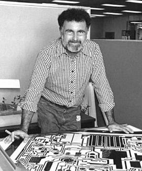
There was a legendary OP-amp fellow named Bob Widar
Here is a magazine avert of his.


national-ad.jpg
 
You should be able to build a pretty good 2way crossover with 2 - 8 pin chips.... Use one chip for each channel. Build one of the opamps on each chip as a low pass filter and the other as a high pass filter... probably half a dozen resistors and a couple of caps for each. The result should be an exceptionally clean sounding crossover.
(My rule is to always keep it simple... minimum parts counts and shortest signal paths always give the best results)
I suppose you're referring to 12 dB/Oct filters. Do you have any schematics laying around and are you willing to share it?
I just wanted to second @gnarly 's approach of using brick wall filters as XO's to extend the region of overlap or simply to avoid stressing a tweeter by crossing too low, or bumping into a nasty resonance with a mid or tweeter metallic dome. Take my Aurum Catus G1 ribbons crossed over at 2k to mate with a 6.5" midbass. IIRC the manufacturer suggests running the tweeter at no more than 1750 Hz, Using a traditional LR4, I might be in trouble, wheres with a -96dB/octave XO I'd be well out of the woods. Conventional wisdom would argue that driver "blending" is an issue, but if so, I haven't noticed it. I have had the opportunity to A/B vs a transient perfect XO using the same drivers: while going back and forth took more time than ideal (passive was kept external for the test), the take home was no preference. This was a Bagby design using drivers with a huge overlap--in other words an ideal situation for the time aligned passive to strut its stuff. Given how affordable multichannel amps have become (meanwhile inductor $$ have soared making even a 2 way passive a tidy investment), there really is little to recommend the approach save simplicity IMO).

I do depart from @garly's approach to SW xo's--I usually use fourth order to avoid the long latencies--also seems with the long wavelengths involved, it is less critical. It is also worth having switchable configurations for low latency implementations if it is used for video playback, but if I understand correctly some of the media services can buffer enough video to allow the audio to catch up.
Have you ever tried linearizing the crossover phase response, for an example with a convolution filter and then switch back and forth? I'd be curious to hear the results, as with 16th order slopes, there should be quite considerable phase shift between drivers.
 
By the way, I don't think it's just a fixed amount of 'latency' involved. As far as I remember, only the first order (6dB / octave) sets the 45 degrees between drivers. Shouldn't higher slopes have uneven latency, relative to the crossover point?
 
I suppose you're referring to 12 dB/Oct filters. Do you have any schematics laying around and are you willing to share it?

Have you ever tried linearizing the crossover phase response, for an example with a convolution filter and then switch back and forth? I'd be curious to hear the results, as with 16th order slopes, there should be quite considerable phase shift between drivers.
I have not. Linear phase filters and time alignment of the drivers are the default choice. Of course, the available literature suggests these delays are inaudible (except at very low frequencies possibly).
 
I suppose you're referring to 12 dB/Oct filters. Do you have any schematics laying around and are you willing to share it?
Ummm ... sorry... I do have designs on hand but they're caught up in an NDA with my partner.
 
Have you ever tried linearizing the crossover phase response, for an example with a convolution filter and then switch back and forth? I'd be curious to hear the results, as with 16th order slopes, there should be quite considerable phase shift between drivers.
Yes, but I've only tried linearizing low order slopes.
This was with two-way speakers that already have active self-powered processing/amplification or a passive xover.
I call that use of FIR, global FIR placed on the input.

Can't say it made much, if any audible difference.

And i really don't think global FIR is the way to go for making speaker corrections. Suboptimal at its best.
I strongly believe in correcting each driver individually, and then tie them together with complementary linear phase xovers.

I also question why would anyone ever try to linearize higher order xovers.
Because if you have the capability to linearize higher-order IIR xovers, you have the capacity to use linear phase xovers, so just use those to begin with.
Besides, high order IIR IIR is sure to suck...so there's no reason to even compare.

Agree with pretty much everything said here although I think there is a use case for linearizing higher order IIR x-overs in that you can do it with lower tap counts compared to a straight higher order FIR linear phase x-over. This is important if you have a tap constrained device like a miniDSP or wish to minimize latency.

Now I seem prefer lower order x-overs to higher order x-overs (even with linear phase) so don't really see the point of pursuing higher order linear phase x-overs but that is a different discussion. :)

Michael
 
By the way, I don't think it's just a fixed amount of 'latency' involved. As far as I remember, only the first order (6dB / octave) sets the 45 degrees between drivers. Shouldn't higher slopes have uneven latency, relative to the crossover point?
Phase between drivers is only indirectly governed by the (final) order of the filter slopes (wrt the acoustic target, not the electric one alone).
However, there are some clean relationsships for common specific filter characteristics that are easy to memorize.
First, we assume we have a symmetrical crossover with equal, mirror-images sloped and transition regions. Further, the acoustic centers of the drivers are all in one plane
Then we have:
- first order gives 90° phase offset between drivers at all frequencies.
- second order Linkwitz-Riley has 180° phase offset throughout, that's why one way must run inverted.
- third order Butterworth sports a constant 240° offset but again one way must be inverted, then giving 90° phase offset
- ... and so on ...

==> Odd order Butterworth acoustic target XO has 90° phase offset between drivers and even order Linkwitz-Riley gives the same phase for all drivers. Same phase response means same group delay for all drivers, one of the assets of Linkwitz-Riley XO.

Note this strictly only applies when the XO point is sort of isolated, no other XO point or roll-offs nearby. These add phase according to their transfer function and if only applied to one of the ways, the fixed phase relationships falls apart (and the summed response isn't completely flat anymore).

For total phase of the summed response, the total phase rotation follows a slightly different pattern:
- first order : 0°
- second and third order : 180°
- fourth and fifth order : 360°
- ... and so on ...

Inverting one way (on top of any required inversion) in an odd order XO gives the same magnitude frequency response. However it creates an (unwanted) additional 180° phase offset, that's why these configurations are discarded but they occasionally pop up in wrongly wired speakers.

With higher orders (>=4 or so) there is significant total group delay below XO with a pronounced peak right at the XO frequency. For very low XO point like from sub to woofer this tends to be quite audible. The higher the XO the lesser the chances for audible issues, IME (but I seldom use anything steeper than 6th order acoustically).
 
Agree with pretty much everything said here although I think there is a use case for linearizing higher order IIR x-overs in that you can do it with lower tap counts compared to a straight higher order FIR linear phase x-over. This is important if you have a tap constrained device like a miniDSP or wish to minimize latency.

Interesting, i hadn't thought of that....having pushed high-order IIR off the table for consideration.
With limited taps, do you find the 'phase resolution' (for lack of a better term) holds better than the FIR filters frequency resolution?
(as per the freq resolution = 1/Time (sec) rule.
Now I seem prefer lower order x-overs to higher order x-overs (even with linear phase) so don't really see the point of pursuing higher order linear phase x-overs but that is a different discussion. :)
Different discussion indeed! I use high order because i keep measuring better polars with them, and it makes getting smooth summation through the entire xover range easier.
 
Agree with pretty much everything said here although I think there is a use case for linearizing higher order IIR x-overs in that you can do it with lower tap counts compared to a straight higher order FIR linear phase x-over. This is important if you have a tap constrained device like a miniDSP or wish to minimize latency.
Isn't that basically the approach than Grimm used in the LS1 (and I'm using it, too)?

First, get a normal "allpass sum" type XO and driver EQ right, in analog or with IIR (strict phase offset, 0° or whatever), then use the time inverse of the emulated/simplified analytical allpass response of that XO as a phase correction convolution kernel.

Such a kernel is very clean as it is not directly created from measurement data and thus can be greatly optimized for tap count... often short enough for direct time-domain convolution, reducing any possible digital artifacts to effectively zero. That said, double precision FFT/iFFT-based convolution is sure clean enough with an analytical kernel, too.
 
Interesting, i hadn't thought of that....having pushed high-order IIR off the table for consideration.
With limited taps, do you find the 'phase resolution' (for lack of a better term) holds better than the FIR filters frequency resolution?
(as per the freq resolution = 1/Time (sec) rule.

Different discussion indeed! I use high order because i keep measuring better polars with them, and it makes getting smooth summation through the entire xover range easier.

Yes, you can get better resolution than a straight FIR filter.

Here are some examples from the ASR Open Source Streamer thread.

This post -> https://www.audiosciencereview.com/...pen-source-streamer-project.20840/post-692795 shows a comparison of a IIR and FIR 4th order LPF at 60 Hz using 2048 taps at 48 kHz, clearly the FIR deviates quite a bit due to lack of taps and low frequency.

This post -> https://www.audiosciencereview.com/...pen-source-streamer-project.20840/post-692834 shows a comparison of an IIR 4th order LPF at 60 Hz and that same filter with a FIR to linearize phase using the same 2048 taps at 48 kHz, now there is no magnitude deviation whatsoever, only hint of the tap constraints are the same wiggles in the phase.

As @KSTR noted this approach is used in the Grimm LS1 -> https://www.grimmaudio.com/wordpress/wp-content/uploads/speakers.pdf.

Michael
 
Agree with pretty much everything said here although I think there is a use case for linearizing higher order IIR x-overs in that you can do it with lower tap counts compared to a straight higher order FIR linear phase x-over. This is important if you have a tap constrained device like a miniDSP or wish to minimize latency.


Michael
Michael, how are you linearizing the phase of the higher-order IIR x-overs?

I just tried using 'Minimum Phase Filters Phase Linearization' in rePhase, for 96dB LRs.
With only 512 taps (48kHz) it linearized the 96dB IIR phase very well !!

But the rePhase output also includes some magnitude rolloff as well, messing up the IIR's xover freq and order.
Here's a 100Hz LR96 high pass example.

rePhase screen, with IIR hpf and FIR filters that are cascaded
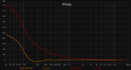
then measured mag and phase

You can see result measured high pass is way off from a 100Hz LR 96

Thanks for any direction here...
I'm psyched how well phase linearized with so few taps...would love to solve mag now...


edit: posted this and then saw your reply...thanks...
will study...
if you see what i need to do differently in rePhase, and it's an easy answer, would appreciate that too


rephase 100Hz LR96 phase lin only.JPG


rephase 100Hz LR96 phase lin only measured response.JPG
 
Michael, how are you linearizing the phase of the higher-order IIR x-overs?

I just tried using 'Minimum Phase Filters Phase Linearization' in rePhase, for 96dB LRs.
With only 512 taps (48kHz) it linearized the 96dB IIR phase very well !!

But the rePhase output also includes some magnitude rolloff as well, messing up the IIR's xover freq and order.
Here's a 100Hz LR96 high pass example.

rePhase screen, with IIR hpf and FIR filters that are cascaded
then measured mag and phase

You can see result measured high pass is way off from a 100Hz LR 96

Thanks for any direction here...
I'm psyched how well phase linearized with so few taps...would love to solve mag now...
View attachment 202358

View attachment 202359

Try rectangular windowing with moderate optimization. Although 96 dB/oct at 100 Hz will probably need more than 512 taps. The deviation you are seeing in magnitude is because you are not using enough taps.

Michael
 
Try rectangular windowing with moderate optimization. Although 96 dB/oct at 100 Hz will probably need more than 512 taps. The deviation you are seeing in magnitude is because you are not using enough taps.

Michael
Sure, of course. Duh on me... forgot my original question as to how does it hold up vs mag.
 
Try rectangular windowing with moderate optimization. Although 96 dB/oct at 100 Hz will probably need more than 512 taps. The deviation you are seeing in magnitude is because you are not using enough taps.

Michael
here's rectangular with moderate optimization...512 taps still
win one, loose the other lol
I see how to experiment...thx again
rephase 100Hz LR96 phase lin only rect and moderate opt.JPG
 
here's rectangular with moderate optimization...512 taps still
win one, loose the other lol
I see how to experiment...thx again
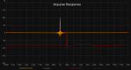
View attachment 202363

It looks like you can minimize the ripple by adjusting the centering:

1651004153204.png


1651004621200.gif


*While the wavelet still looks kind of "bad" visually, I do not know how audible the effect is in practice:

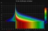
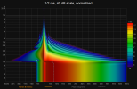
1651006116838.png 1651006122869.png 1651006922765.png 1651006940391.png 1651006968052.png 1651006986159.png
 
Last edited:
From my experiences, (and not taking the choice between dsp and analog in account) and what i hear from many others (also real electronic engineers) is that opamps (at least the good ones) are good in small signal amplification and buffering in preamps, dac's and so, but not good in hi gain applications (power amplifiers) where mosfets are way better. What is true about it i don't know, and i have no scientific base on this claim. But if i open up solid state (class A or AB) power amps that i like, it's mostly mosfet based, and when i don't like it's very often opamp based. While with preamplifiers or dac's i don't have that. Class D and digital amps are something else off course...

But i'm no expert, so this is just anecdotical, not an objective scientific based constation. So feel free to prove me wrong. But what i do know is that analog active crossover need to be tailored to the speaker just like other crossovers, and that premade units with fixed slopes and crossover points in almost all cases are far from optimal. So on that DSP or wel designed analog passive crossovers are way better and in most cases a way more logical choice.
 
It looks like you can minimize the ripple by adjusting the centering:

View attachment 202595


View attachment 202602


*While the wavelet still looks kind of "bad" visually, I do not know how audible the effect is in practice:

View attachment 202633 View attachment 202634 View attachment 202635 View attachment 202636 View attachment 202637 View attachment 202638

Nice work.
Yes, i would expect moving impulse peak past the FIR filter center gives more control over all-pass behavior, just as moving the peak towards the filter's start gives more control over minimum phase behavior.
I like the tutorial from EclipseAudio, which describes minimum, linear, and maximum phase use of FIR. https://eclipseaudio.com/fir-filter-guide/

I don't have much time to experiment right now, but i just made a quick comparison of:
a. phase linearizing a LR96 xover @100Hz, where the FIR filter precedes the summation of the high-pass and low-pass sides.
b. summing straight linear phase LR96 high pass and low passes

I used 2048 taps for a. the min phase linearization, and for b. 1024 taps per linear phase filter.
I was trying to see how i would utilize a minDSP 2x4HD for the LR96 choice. I scaled down the 2x4HD's max 4096taps at 96kHz, to 2048 max 48kHz.
(damn shame the thing only runs FIR at 96kHz)
My processor runs at 48k and i do like real time measurements :)

Anyway, here is the rePhase linearization of the 100Hz LR96 using 2048 taps, 80% centering, rectangular windowing, and moderate opt.
rephase 100Hz 2048taps LR96 phase linearization 80% rect mod.JPG


And here is a straight 100Hz LR96 linear phase xover, each side getting 1024 taps, with impulse centering, cosine windowing, and no opt.
Fird 100Hz 1024taps 96dB LR lin phase highpass and low pass summed.JPG


Either would work i think, but i'd just stick with straight linear phase xovers based on this (waaaaay too quick analysis)
 
Back
Top Bottom