• WANTED: Happy members who like to discuss audio and other topics related to our interest. Desire to learn and share knowledge of science required. There are many reviews of audio hardware and expert members to help answer your questions. Click here to have your audio equipment measured for free!

Keith_W DSP system

ernestcarl

Major Contributor
Joined
Sep 4, 2019
Messages
3,113
Likes
2,330
Location
Canada
@ernestcarl if you want to look at the difference between the initial measurement and corrected measurement, here it is:

View attachment 350536

The volume on the subwoofer is maxed out to give plenty of scope for cutting.

Ah... some resemblance there with your exported measurements in the previous room setup orientation:

1708275131905.png


It is all windowed, though.
 

OCA

Addicted to Fun and Learning
Forum Donor
Joined
Feb 2, 2020
Messages
679
Likes
499
Location
Germany
It's just that Uli's are better
You should be happy that you can be sad about your filters being not as good as Dr Uli's :) The guy wrote Acourate on his own, I guess people who would do better than him are numbered on this planet.
 

3ll3d00d

Active Member
Joined
Aug 31, 2019
Messages
212
Likes
176
Hmm, so you are saying that a 64k tap filter is the same as a 128k tap filter if they both have exactly the same settings for phase correction, delays, etc? I have to say I am a bit skeptical, but there is only one way to find out.
The 128k filter will have 2x the delay and 2x the frequency resolution as you said earlier, might be audibly the same though. I think what he's saying is that you don't have to use a centred impulse, you may accept shorter delay (not centred impulse) and some imperfection in the phase correction for example.

In acourate terms, a more common example would be using prefilters (macro 0) to allow for minimum phase filters to be embedded in the final result.
 
OP
Keith_W

Keith_W

Major Contributor
Joined
Jun 26, 2016
Messages
2,660
Likes
6,064
Location
Melbourne, Australia
You should be happy that you can be sad about your filters being not as good as Dr Uli's :) The guy wrote Acourate on his own, I guess people who would do better than him are numbered on this planet.

You are right! I watched the filters being created in front of me, saw what he was doing, mentally compared his process with mine. Then I had to write it all down somewhere. And then I heard the effect of those filters and it is quite simply amazing. What I do not understand is WHY his soundstage sounds so much better than mine, mine sounds restricted, as if it's all in a little box. His sounds open and natural. I think the biggest difference between his correction and mine is that I may have inappropriately linearized the drivers. He said "it is better to leave it than to do the wrong correction". So that is where I will start first.

Now the real question is, whether I would be able to replicate it? I am going to store his filters in a safe place, then throw out everything I have done and start again from scratch.
 

dualazmak

Major Contributor
Forum Donor
Joined
Feb 29, 2020
Messages
2,850
Likes
3,047
Location
Ichihara City, Chiba Prefecture, Japan
You are right! I watched the filters being created in front of me, saw what he was doing, mentally compared his process with mine. Then I had to write it all down somewhere. And then I heard the effect of those filters and it is quite simply amazing. What I do not understand is WHY his soundstage sounds so much better than mine, mine sounds restricted, as if it's all in a little box. His sounds open and natural. I think the biggest difference between his correction and mine is that I may have inappropriately linearized the drivers. He said "it is better to leave it than to do the wrong correction". So that is where I will start first.

Now the real question is, whether I would be able to replicate it? I am going to store his filters in a safe place, then throw out everything I have done and start again from scratch.

Very nice to hear the recent storey. Yes, we often experience such situations. I am very much looking forward to hearing your further progress.:)

The objectively optimized XO EQ Delay, etc. (slightly downward "flat" Fq response and phase linearity) would not always give the best subjective listening enjoyments.
And,
The best subjectively/objectively optimized configurations for yourself would not always be the best for other people's subjective preference.

These are fundamental and interesting (and enjoyable) aspects of our intensive audio and room acoustic tunings.

At least in my case, throughout my efforts in the past several years, I learned that "the simpler, the better (for subjective listening sensations)" in DSP tuning, and also I found careful room acoustic tuning/treatment would be similarly (or more) critical as/than DSP tuning...
 
Last edited:

OCA

Addicted to Fun and Learning
Forum Donor
Joined
Feb 2, 2020
Messages
679
Likes
499
Location
Germany
You are right! I watched the filters being created in front of me, saw what he was doing, mentally compared his process with mine. Then I had to write it all down somewhere. And then I heard the effect of those filters and it is quite simply amazing. What I do not understand is WHY his soundstage sounds so much better than mine, mine sounds restricted, as if it's all in a little box. His sounds open and natural. I think the biggest difference between his correction and mine is that I may have inappropriately linearized the drivers. He said "it is better to leave it than to do the wrong correction". So that is where I will start first.

Now the real question is, whether I would be able to replicate it? I am going to store his filters in a safe place, then throw out everything I have done and start again from scratch.
I know what you mean. I like to call that "throttled" sound. Although this is not a very relevant measure for small rooms, you "might" see the difference in C80 graphs. Too much correction usually twists peak energy times of certain frequencies.
 
Last edited:
OP
Keith_W

Keith_W

Major Contributor
Joined
Jun 26, 2016
Messages
2,660
Likes
6,064
Location
Melbourne, Australia
THREE METHODS FOR SUBWOOFER TIME ALIGNMENT

As I mentioned in the previous post, Dr. Uli has a different subwoofer time alignment procedure than what I use. I am familiar with two of them, but I have never seen the third. What's more, he cross-references the time alignment with each other and he spends 3x as much time on this procedure than I do.

These are the three methods:

1. Time alignment by impulse response. Delay the tweeter by 1000 samples, then align the tweeters. Look for the position of the subwoofers then adjust. This is well described in @mitchco's book, I highly recommend it (no, I don't earn a commission from Amazon links :p)
2. Time alignment by sinewave convolution. Described here. The advantage of this method is that it compares the subwoofer with the woofer, and you are able to see the initial impulse as well as the steady state impulse.
3. Time alignment by subwoofer-woofer alignment. This is the method I haven't seen, and I will describe.

TIME ALIGNMENT BY SUBWOOFER-WOOFER ALIGNMENT

1708315906984.png


1. First we obtain a "ballpark" figure for what we expect the delay to be. Measure the distance from woofer to MLP, and the sub to MLP. In my case, the difference between the two was 1.3m. To convert distance to time (assuming speed of sound is 343m/s), it is (1.3/343) = 0.0379s, or 3.79ms. To convert 0.0379s into samples, it is (48000 * 0.013), or 182 samples.

2. The first step is to time align the woofer to the tweeter using the standard method described by @mitchco (also described below). The next step is to time align the sub to the woofer.

1708326596281.png


3. Create this filter.
- For the sub: use the standard crossover that you are planning to use.
- For the woofer: Save XO1L48/R48 as XO2L48/R48, i.e. your woofer will be receiving exactly the same signal as your sub.
- For mids and tweeters: leave them alone.
- Generate a multiway filter from the above.

4. We will be measuring twice, once with the woofers+mids turned off, and again with the sub+mids turned off. This will give us two curves, sub+tweeter and woofer+tweeter when we finish taking the sweeps. Take two sweeps, and the result will look like the curve above. Overlay the curves and work on one channel at a time.

1708315254183.png


5. Switch to the Step response. You will see the above curve.

1708315471044.png


6. Read the timing of the woofer peak and subwoofer peak, then rotate the subwoofer curve by the exact number of samples. In this case, the woofer was at 6045, and the sub was at 6369, the difference is 324 samples. This corresponds to (324/48000 * 1000) = 6.75ms. But wait, the calculation above says that the delay should be 182 samples or 3.79ms. This is because there are other types of delay at play here, which is why we don't time align by geometry alone.

7. This method only time aligns the initial impulse. So now we need to time align the steady state. Take note of the 324 sample delay, and use the sinewave convolution method to cross-reference it.
 
Last edited:
OP
Keith_W

Keith_W

Major Contributor
Joined
Jun 26, 2016
Messages
2,660
Likes
6,064
Location
Melbourne, Australia
TIME ALIGNMENT BY SINE WAVE CONVOLUTION

1708318181976.png


1. Follow steps 1-4 from the above procedure. Or reuse the pulses generated from the above procedure. You will end up with the above curve.

2. Generate an 80Hz sinewave. Generate-Tone Generator. 80Hz sinewave, no rectification, signal length 65536. Result into Curve 3.

1708318346907.png


3. Convolve the Sub+Tweeter Pulse with the sinewave, result into Curve 4. Do the same with the Woofer+Tweeter pulse, result into Curve 5. You will get the above result.

1708318398641.png


4. Now we zoom in to the frequency peak and look at the difference in gain between the two pulses. Here it is 13dB. Adjust the gain of the subwoofer pulse (cyan) until they match.

1708318699608.png


5. Now we switch to the Impulse window and zoom in. This is what we see.

1708318931384.png


6. From the previous method, we know that the subwoofer is 324 samples delayed to the woofer. So we rotate the sub by 324 samples to the left. Now the initial impulses align, but the steady state is not aligned.

1708319146983.png


7. We read off the peaks from the sub in the steady state, in this case the sub is 10218, and the woofer is 10184, or 34 samples to the right. Now we rotate the sub by -34 samples, so we see that the steady state is aligned, but the initial impulse is not. The total is 324 + 34 = 358 samples. When I asked Uli why he aligns the steady state and not the initial impulse, he said "the initial impulse is short".
 
OP
Keith_W

Keith_W

Major Contributor
Joined
Jun 26, 2016
Messages
2,660
Likes
6,064
Location
Melbourne, Australia
TIME ALIGNMENT BY DELAYED TWEETER

My method is a modification of the method described by Mitch in his book, but it is exactly the same concept.

1708319544398.png


1. First we create our crossover and convolve all the driver linearization, reverse AP filters, etc. into it. Then we create the above folder structure and copy the crossover into every subfolder. For the first subfolder "00 Tweeter delay +1000", we open the tweeter crossover, rotate it by +1000 samples, then save it. Create a Multiway filter with the tweeter delay and save it in the same subfolder. Then set the mic at the MLP, set "Project Working Directory" to the DUT (driver under test), and start measuring.

1708319799464.png


2. Take a sweep with the non-DUT drivers turned off (I hit mute for those channels on my mixer). Result looks like above.

1708319993183.png


3. Switch to the "Time" window and zoom in. The subwoofer impulse is very low volume, take note how much I had to zoom in to see it. Acourate centres the tweeter at position 6000. But because the tweeter has been delayed by 1000 samples, the subwoofer peak should be at position 5000.

1708320175871.png


4. To help us find the subwoofer peak, we load the subwoofer XO (XO1L48) into curve 2. Because we are using 65536 taps, Acourate centres the XO in the middle, i.e. at position 32768. The tweeter is centred at position 6000. So we have to rotate the XO by (32768-6000), or -26768 samples. However, we delayed the tweeter by 1000 samples, so we rotate it 1000 samples to the left. Total, -27768 samples. The result looks like the above, it clearly indicates where the subwoofer impulse should be.

1708320628488.png


5. Read off the subwoofer impulse, in this case it is at position 4928. We expect the subwoofer peak to be at position 5000, so the sub is 72 samples too early. *Note: I am using a different measurement to illustrate this procedure than the ones used in the above examples, this is why the values are different. Uli over-wrote his procedure when he did it. The reason this example is so far off (72 samples early vs. 358 samples delayed) is because this one has a reverse AP filter in the subwoofer which advances the time.

1708320941018.png


6. Now we take a verification measurement with the subwoofer rotated by +72 samples. If we FDW it, we can clearly see that the subwoofer is time aligned.

Previously, I used this procedure alone for all subwoofer time alignment. However, I now realize that this only aligns the initial impulse of the subwoofer, and not the steady state behaviour. This method works very well for shorter wavelengths (i.e. the woofer and the midrange driver), but it is not great for subwoofers. From now onwards, I will use this method to find the initial delay, then use the sinewave convolution method to align the steady state for the subs.

I should also note that I get different values for subwoofer timing every time I do a measurement. This is normal, subwoofers do not behave consistently. I know that @OCA takes 5 or more sweeps and discards the ones he does not like, perhaps I should start doing the same.
 
Last edited:

MaxwellsEq

Major Contributor
Joined
Aug 18, 2020
Messages
1,752
Likes
2,646
He said "it is better to leave it than to do the wrong correction". So that is where I will start first.
That's reassuring, since I have a similar point of view (without anything like his erudition and experience).
 

ernestcarl

Major Contributor
Joined
Sep 4, 2019
Messages
3,113
Likes
2,330
Location
Canada
The 128k filter will have 2x the delay and 2x the frequency resolution as you said earlier, might be audibly the same though. I think what he's saying is that you don't have to use a centred impulse, you may accept shorter delay (not centred impulse) and some imperfection in the phase correction for example.

In acourate terms, a more common example would be using prefilters (macro 0) to allow for minimum phase filters to be embedded in the final result.

Yep.

I think I see why in Acourate one may want to lump everything -- HPF, LPF, time offset delays, all magnitude and phase correction -- into the FIRs, but it makes it seem unnecessarily like more taps and more LF filter resolution and longer processing latencies = better correction results.

I said "the task can be split" and here's one diagram to illustrate using a QSC processor:

1708331859926.jpeg


My setup is maybe not all that complicated given the only crossovers I need to work around are between the sub and mains, but the principle of splitting the DSP works out fine.

Desk Setup Sub EQ:
1708332338691.png


Impulse centering is adjusted here to reduce total processing latency and where 8k taps is already adequate for the magnitude and partial phase correction.

BUT, in reality, I am using the FIR filter in this channel only to apply phase EQ and relegated the rest in JRiver's DSP studio:
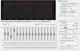
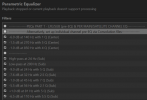
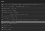
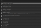
1708332840587.png 1708332868485.png 1708333599754.png 1708333613331.png
*SL and SR are swapped with Left and Right to re-route between two different setups (couch and desk).
 
Last edited:
OP
Keith_W

Keith_W

Major Contributor
Joined
Jun 26, 2016
Messages
2,660
Likes
6,064
Location
Melbourne, Australia
@ernestcarl, a friend of mine who uses Acourate does something similar to you. He separates out all the corrections into modules, which he arranges into a pipeline to be processed by CamillaDSP. I suppose that makes it easier to make changes, you can swap out modules instead of redoing the entire filter which is what I am doing at the moment. Are there any other advantages?
 

ernestcarl

Major Contributor
Joined
Sep 4, 2019
Messages
3,113
Likes
2,330
Location
Canada
@ernestcarl, a friend of mine who uses Acourate does something similar to you. He separates out all the corrections into modules, which he arranges into a pipeline to be processed by CamillaDSP. I suppose that makes it easier to make changes, you can swap out modules instead of redoing the entire filter which is what I am doing at the moment. Are there any other advantages?

I agree with him that making changes can be quicker... I don't need to re-adjust the phase response and generate a new FIR filter every time I want to make some adjustment to a magnitude parameter e.g. -4dB instead of -1.5dB at 300Hz as well as shelving filters as broad tone controls on the fly. I think this is not just an advantage but is necessary in some time critical applications like in live sound design.
 

dualazmak

Major Contributor
Forum Donor
Joined
Feb 29, 2020
Messages
2,850
Likes
3,047
Location
Ichihara City, Chiba Prefecture, Japan
Again, please excuse me sharing my naive general thoughts...

In any DSP processing, XO, EQ, Gain, Delay, Phase-Inversion, etc. are not independent with each other but more or less affect each other, as we know well. Therefore, if we try to complete/optimize these tuning items only within DSP, we may possibly end up in a muddy endless tuning loops/spirals.

From this perspective, I believe that we should not insist on putting all these tuning processes on DSP alone. In particular, with regard to relative gain adjustment (tone control in multiple-SP-driver system), we should not hesitate to effectively use HiFi control amplifiers and/or HiFi integrated amplifiers at the analog stage after the DAC for flexible gain adjustment (tone control) for preference of listener (yourself) and audiences as well as depending on the nature/genre of the music you would enjoy.
Edit: Here I mean to use slight and coarse (wide band) gain (tone) adjustment/tuning at analog stage "after" we could finalize the DSP configuration including fine EQs.
At least in my DSP audio system, I like "the simpler, the better" tuning in DSP (including 0.1 msec precision time alignment), and in analog stage I flexibly use four HiFi "integrated amplifiers", and L&R active subwoofers having flexible-Fq-LP-filter(-24 dB/Oct), gain/volume dial, and phase-inversion all of them can be controlled by a remote while sitting at my listening position. Please refer here for details of my latest setup, and here as well as here for example cases of safe and flexible tone control.
WS00006960.JPG

BTW, I noticed with a little surprise that your tone-burst sine wave matching between subwoofer and woofer (4., 5., 6. in your above intensive post #188) seems to be almost identical to what I have primitively done in my setup measured by using Adobe Audition 3.0.1 (ref. here, here and here).:D
 
Last edited:
OP
Keith_W

Keith_W

Major Contributor
Joined
Jun 26, 2016
Messages
2,660
Likes
6,064
Location
Melbourne, Australia
From this perspective, I believe that we should not insist on putting all these tuning processes on DSP alone. In particular, with regard to relative gain adjustment (tone control in multiple-SP-driver system), we should not hesitate to effectively use HiFi control amplifiers and/or HiFi integrated amplifiers at the analog stage after the DAC for flexible gain adjustment (tone control) for preference of listener (yourself) and audiences as well as depending on the nature/genre of the music you would enjoy.

I do not agree with that, sorry. What you are suggesting is a 4 band graphic equalizer with the bandwidth set by the bandpass. This is an extremely coarse adjustment and is only useful for setting broad tilt. Why bother with that when I have JRiver, which has its own parametric EQ? Or better still, I have Acourate Convolver. I can switch between filters by remote control from the comfort of my sofa by pushing a button. The music does not stop. I am not sure if EKIO has the same functionality.
 

gnarly

Major Contributor
Joined
Jun 15, 2021
Messages
1,037
Likes
1,471
@ernestcarl, a friend of mine who uses Acourate does something similar to you. He separates out all the corrections into modules, which he arranges into a pipeline to be processed by CamillaDSP. I suppose that makes it easier to make changes, you can swap out modules instead of redoing the entire filter which is what I am doing at the moment. Are there any other advantages?

I like to fully separate speaker processing components. Gain, polarity, delay, FIR filters, and IIR filters...... all get their own independent controls.
I think getting gains, polarities, and delays correct at time of raw measurements of each driver section, makes for cleaner, easier to analyze if all is working well, FIR files.
It's huge advantage not to put any fixed relative delay time into the FIR filter, by shifting impulse centers around,... ime/imo. I like to use the same size, impulse centered FIR file on all driver sections, such that delays simply become time-of-flight to acoustic centers. Helps with the processing smell test, and allows easy FIR filter substitutions.

I like global input IIR filters, used for either room tuning, tone control, (or a system high pass if subs needs a hpf) to be in a separate bank.
Likewise, if I want to use FIR room correction, I like it to be separate from the speaker management processing above.

I think going the 'separate' route helps me isolate and define logically the 'order of operations' so to speak....and from that get a better grasp on what can and can't be corrected.
And what type measurements are needed for the tuning/correction. (for instance speaker tuning vs room tuning)

Like ernestcarl posted an example of above, I use QSC to do all this...here's a schematic of a LCR setup.
In addition to separating components, it lets me make the adjustments dualazmak was describing that can be made with our equipment outside the single DSP file(s)

I don't mean to be dissing the single DSP file approach in any way....I just find it too difficult to juggle,m compared to my straightforward "kiss" way of thinking.

syn11 qsys schematic snip 12-14-22.JPG
 
OP
Keith_W

Keith_W

Major Contributor
Joined
Jun 26, 2016
Messages
2,660
Likes
6,064
Location
Melbourne, Australia
I wouldn't say that looks "KISS" to me, it looks awfully complex. Why are you using IIR filters together with FIR filters? And why do you have gain and I delays applied multiple times in the pipeline?

And BTW, even though I have all the filters baked into a single file, I have my work saved during multiple stages in the process in clearly labelled folders. If I want to change something, I can go back to that stage of the process and simply take another direction.
 

3ll3d00d

Active Member
Joined
Aug 31, 2019
Messages
212
Likes
176
Basically any non trivial DSP filter chain is commonly complicated to reason about irrespective of how you try to model it and whether it comes out as a single filter or n stages :)
 

gnarly

Major Contributor
Joined
Jun 15, 2021
Messages
1,037
Likes
1,471
I wouldn't say that looks "KISS" to me, it looks awfully complex. Why are you using IIR filters together with FIR filters? And why do you have gain and I delays applied multiple times in the pipeline?
Sorry, that was probably a bad schematic to show....being an LCR with some extra stuff thrown in.

I use IIR filters together with FIR filters, because I've found system hpf and lpf are the source of pre-ring that doesn't cancel. ....Complementary linear phase xovers are fine, they cancel pre-ring. But there is no summation for linear phase hpf or low pass on the spectrum ends.
I could just embed an IIR hpf in the FIR file, but then I get the limited frequency resolution of the FIR file (16k taps @ 48kHz is all I've got with qsys). So I jst use IIR for hpf with full resolution.
Plus, I can easily turn the separate IIR hpf on or off.....don't need it until really cranking.

The gains serve different purposes.
The light blue 15ch gain is the master volume (controlled by the red master slider).
The various colored gains associated with each driver section (controlled by colored sliders) are essentially my form of real time EQ. I like this method much better than para EQ or shelving. And Helps make a bunch or easy house curve presets. All driver gains at 0 dB, means flat response.

The delays serve different purpose too.
The rainbow block preceding the 15ch gain is for quasi-anechoic speaker tuning. There, relative gains, and timing delays are established that never vary.
The sub, mains, and center delay are for changes in physical listening distance, when trying placements.

Again my apologies for a complicated example of separating components.
Here's an example of stereo quickie that that took about 10 min to put together. I used a analog line out, but of course could have put in AES67, USB, Dante, etc, outs
Purpose is only to show ease, and simplicity.

simple stereo qsys.JPG
 
Top Bottom