• WANTED: Happy members who like to discuss audio and other topics related to our interest. Desire to learn and share knowledge of science required. There are many reviews of audio hardware and expert members to help answer your questions. Click here to have your audio equipment measured for free!

Importance of impulse response

Holmz

Major Contributor
Joined
Oct 3, 2021
Messages
2,020
Likes
1,244
Location
Australia
Studies have shown that listeners don't have a preference between speakers that have time aligned driver impulses, and speakers without time aligned driver impulses.

Studies how shown than “many” people.
Not ALL people.


Can the impulse response show the distortion of the speaker?

Yeah distortion in the time domain.
Group delay also shows the time distortion with respect to frequency.
 

ernestcarl

Major Contributor
Joined
Sep 4, 2019
Messages
3,115
Likes
2,337
Location
Canada
Apologize for hijacking the the thread but it seemed appropriate to post here rather than start a new thread.

Finally after 4 years I finally realised how I can zoom into the impulse response and see the first 5 or so seconds and I can actually see the shape of the response.

I have attached the response of my Audiolense DSP tri-amp system with its crossovers done through the DSP. Compression driver and 15 inch mid and dual subs in a very small but heavily acoustically treated room. And no timing reference or loopback in measuring.

It looks good to me but I am struggling to fully understand if is properly time aligned, as on paper with Audiolense it should be. If anyone would like chime in...


View attachment 242385

The “unfiltered” IR graph view is heavily HF biased so you won’t glean enough from looking at it alone by itself. But what you’re showing (very much zoomed in time) though seems perhaps somewhat weirdly mangled (?) at a glance. It might be helpful to look at some example IR plots posted in Amir’s speaker reviews.

If it’s a multiway system, you could look at the IR overlays view for individual drivers and see how closely they overlap each other (time reference offsets have to be correctly set), then compare those to their resulting sum. Same type of superimposed overlays view should also be observed for the phase and step response.

Simple example from one of the speakers in my main listening room:

1668069201689.png


1668069208392.png
 
Last edited:

antcollinet

Master Contributor
Forum Donor
Joined
Sep 4, 2021
Messages
7,904
Likes
13,389
Location
UK/Cheshire
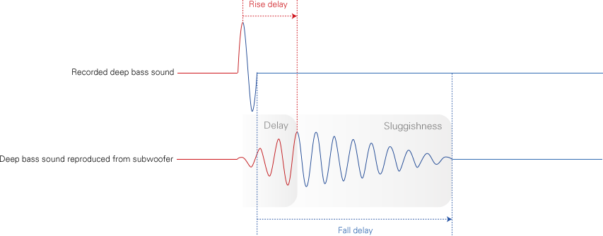
So companies that say stuff like this are basically lying?


seikaku.png

Yes - that is complete nonsense. Any transducer that did that would be totally unable to reproduce music. There is no resemblance between the input signal and output signal. It is not even LOFI.
 
Last edited:

KSTR

Major Contributor
Joined
Sep 6, 2018
Messages
2,843
Likes
6,382
Location
Berlin, Germany
The “unfiltered” IR graph view is heavily HF biased so you won’t glean enough from looking at it alone by itself
Exactly!
Visual inspection of Impulse Response is futile. Use Step Response instead (which is a unit step convolved with the Impulse Response), to have a chance seeing what's happening at low frequencies. And use different horizontal zoom levels, that is, zoom in on the leading edge to about 1ms to see high/mid details.
 

KSTR

Major Contributor
Joined
Sep 6, 2018
Messages
2,843
Likes
6,382
Location
Berlin, Germany
Studies have shown that listeners don't have a preference between speakers that have time aligned driver impulses, and speakers without time aligned driver impulses.
Other studies have shown when you have the exact same speaker with the exact same crossover slopes etc, the linear phase version is mostly preferred over the common allpass phase version. The more crossover points you have at lower frequencies (<1kHz) the stronger the preference. Subwoofer XO at ~80Hz is especially bad for "speed" and "compactness" of bass transients.

Remember, "transient" does NOT mean a sharp and short pulse here, rather it means a short but tonal burst of just a few cycles of a sine wave with a smooth envelope, often called "blips". Those are even standardized, by now (CEA-2010 Burst, 6.5 cycles, Hann window envelope). Phase distortion now manifests itself in different arrival times of those bursts at different frequencies (the lower ones coming later, typically) even though they started at the same time (or had their "center of gravity" aligned) in the source signal. And that's what we can perceive in a direct comparison, some more than others...
 

Trdat

Addicted to Fun and Learning
Forum Donor
Joined
Sep 6, 2019
Messages
968
Likes
397
Location
Yerevan "Sydney Born"
The “unfiltered” IR graph view is heavily HF biased so you won’t glean enough from looking at it alone by itself. But what you’re showing (very much zoomed in time) though seems perhaps somewhat weirdly mangled (?) at a glance. It might be helpful to look at some example IR plots posted in Amir’s speaker reviews.
Yes but isn't all I need to see the 3 peaks of the tweeter, mid woofer and bass? Doesn't the above show those 3 peaks?
If it’s a multiway system, you could look at the IR overlays view for individual drivers and see how closely they overlap each other (time reference offsets have to be correctly set), then compare those to their resulting sum. Same type of superimposed overlays view should also be observed for the phase and step response.
Multiway in what way? Its a 3 way but tri-amped.

Which tab is the IR overlays? Overlays or the IR Window?
Simple example from one of the speakers in my main listening room
How do I get the woofer and tweeter to show seperately?
 

Trdat

Addicted to Fun and Learning
Forum Donor
Joined
Sep 6, 2019
Messages
968
Likes
397
Location
Yerevan "Sydney Born"
Exactly!
Visual inspection of Impulse Response is futile. Use Step Response instead (which is a unit step convolved with the Impulse Response), to have a chance seeing what's happening at low frequencies. And use different horizontal zoom levels, that is, zoom in on the leading edge to about 1ms to see high/mid details.
Isn't what I posted the step response? Or are you sugggesting to show both the step response and ETC together?
 

JanesJr1

Addicted to Fun and Learning
Joined
Jun 9, 2021
Messages
506
Likes
451
Location
MA
So companies that say stuff like this are basically lying?


seikaku.png
This is it: an audio layman's perception of the impulse response question. That's me. Why doesn't this make sense?

Never mind the vocabulary, whether it describes "fast v slow" or "sharp v soft", what is the effect of this difference on perceived fidelity? How could the two cases not sound different?

In the opposite direction, I have two audiophile headphones, and with one a very sharp, synthesized transient sounds like a fast, loud, instantaneous snap of electricity. On the other, the same transient sounds more like a handclap (less immediate.) Why? What physical phenomenon explains it, if not the one in the graph above?

With more continuous tones or live music, how are such speaker differences described, explained and if possible measured?
 

dominikz

Addicted to Fun and Learning
Forum Donor
Joined
Oct 10, 2020
Messages
806
Likes
2,638
This is it: an audio layman's perception of the impulse response question. That's me. Why doesn't this make sense?

Never mind the vocabulary, whether it describes "fast v slow" or "sharp v soft", what is the effect of this difference on perceived fidelity? How could the two cases not sound different?

In the opposite direction, I have two audiophile headphones, and with one a very sharp, synthesized transient sounds like a fast, loud, instantaneous snap of electricity. On the other, the same transient sounds more like a handclap (less immediate.) Why? What physical phenomenon explains it, if not the one in the graph above?

With more continuous tones or live music, how are such speaker differences described, explained and if possible measured?
The problem with the graph above is that it gives an example with descriptions that do not reflect the physical reality and are threfore misleading.

E.g. the first picture doesn't show a "recorded deep bass sound" but an impulse which when transformed into the frequency domain via Fourier transform would have infinite spectrum width (so a lot of high frequencies too!).

Remember that any time-domain function can be transformed into an equivalent frequency (magnitude + phase) response and vice-versa. I.e. the impulse and frequency responses of the same system show the same data - just a different view of it.

This can be difficult to explain in just a few words and without math - but there are e.g. some nice visual explanations on ASR and elsewhere.

In addition, it appears humans are in general far more sensitive to small frequency response magnitude differences than many phase or time domain differences. This means that in controlled blind tests people often wouldn't be able to reliably differentiate between sounds with the same frequency magnitude spectrums but different time domain function shapes (within reason, of course).

Many times the feeling of "speed" relates simply to the lack of bass resonance peaks, or less bass, or more treble, or some combination of these.

Hope this helps!

EDIT: Let me provide some references, perhaps it will be helpful to some!
  • Link to an AudioXpress article on audibility of phase with comments from Dr. Floyd Toole, Dr. Wolfgang Klippel, Andrew Jones and James Croft
  • Link to ASR post #1 - Illustrations of how high-passing or low-passing and ideal pulse impacts the signal in frequency and time domain. Also an illustration of how the step and impulse response looks like when limited to the human hearing range (20Hz-20kHz) in an idealized case.
  • Link to ASR post #2 - Illustration of how typical loudspeaker crossover impacts the impulse and step response, comparison between a real loudspeaker response and a similar idealized simulated response.
  • Link to ASR post #3 - A very nice illustration showing how a sum of 3 sine waves of different frequencies looks like in the time and frequency domains (Fourier transform)
 
Last edited:

antcollinet

Master Contributor
Forum Donor
Joined
Sep 4, 2021
Messages
7,904
Likes
13,389
Location
UK/Cheshire
This is it: an audio layman's perception of the impulse response question. That's me. Why doesn't this make sense?

Never mind the vocabulary, whether it describes "fast v slow" or "sharp v soft", what is the effect of this difference on perceived fidelity? How could the two cases not sound different?

In the opposite direction, I have two audiophile headphones, and with one a very sharp, synthesized transient sounds like a fast, loud, instantaneous snap of electricity. On the other, the same transient sounds more like a handclap (less immediate.) Why? What physical phenomenon explains it, if not the one in the graph above?

With more continuous tones or live music, how are such speaker differences described, explained and if possible measured?
Because if a speaker did as shown with an "in bandwidth" signal, it would not be possible to recreate any musical waveform.

Sure - output won't be the same as input, because you've got discontinuities (meaning infinet bandwidth) at the start and stop of the input. The result would be a rounding at the start, and possibly an over shoot, and or rounding at the end - perhaps with a small oscillation (assuming the main part of the waveform is within bandwidth of the transducer.

A transducer is a minimum phase system. That means the movement of the cone basically tracks the input signal as long as the input signal is within the bandwidth capability of the transducer. There will be lag and/or lead (phase shift) possible ringing at transients (eg if trying to track a square wave - but that is out of bandwidth) but you won't get additional (high magnitude) vibrations - or at least, when you do (if driven beyond limits), that is audible distortion.


EDITED TO ADD - plus, looking at that daft input output waveform again. The output continues to get bigger even after the input has stopped - how on earth does that happen. Where is the energy coming from to increase the magnitude of the speaker movement?

Utter nonsense.
 
Last edited:

ernestcarl

Major Contributor
Joined
Sep 4, 2019
Messages
3,115
Likes
2,337
Location
Canada
Yes but isn't all I need to see the 3 peaks of the tweeter, mid woofer and bass? Doesn't the above show those 3 peaks?

Multiway in what way? Its a 3 way but tri-amped.

Which tab is the IR overlays? Overlays or the IR Window?

How do I get the woofer and tweeter to show seperately?

Sorry, I meant it as simple only in the way that it’s only a tweeter and a woofer where the IR peaks overlay on top of each other exactly in the graph view. Most speakers won’t have this…

You don’t need to see three peaks in the step response also. You can have multiple peaks like in the graphic Kimo showed earlier: step, ETC and others things were all bunched into one single graph — those are all just different graphical ways of representing the same IR.

You could already kind of guess in that “bad” IR example that the system was a multiway whose driver alignment appears to be especially spread out or smeared way too far apart in time.

The directivity and on-ax freq magnitude response may have looked perfectly nice on a spinorama, but the actual transient response — if you look at its wavelet, for example, would not be so good… or lined up together as neatly in time when it’s viewed from a different view — a view in which takes time into far more consideration.

There are two IR views in the main REW window (one can show “filtered” version). The Overlays window is a separate window altogether where you can superimpose multiple measurements (overlay) depending on tabbed view title you pick e.g. step, SPL, phase etc.

You will want to measure each component of the system separately (which may include the reflex port) if want to understand why their summed step response, for example, appears the way it does.
 
Last edited:

kemmler3D

Major Contributor
Forum Donor
Joined
Aug 25, 2022
Messages
3,502
Likes
7,134
Location
San Francisco
Studies have shown that listeners don't have a preference between speakers that have time aligned driver impulses, and speakers without time aligned driver impulses. Does this answer your question? As long as the frequency response is even and follows the listeners preferred curve, how the impulse response looks is mostly unimportant.
No, that has nothing to do with my question, sorry. I also don't 100% believe those results, as others have said, those tests were conducted before we could use convolution filters to get fully time-aligned responses.

What I'm asking is whether the system needs the ability to reproduce (say) 20hz to reproduce a true transient signal. A theoretical dirac-function transient includes all frequencies, like white noise but all at the same time. If you look at a spectrogram of a transient, it looks like a vertical line across the full bandwidth. In real life with a physical transducer, what is the effect of (presence of lack of) low bass on fast transients?

If you think about the effect on sound you get from filtering an impulse click and then listening to it, lack of bass is audible even if the signal only lasts 0.1ms. So to jump to my conclusion here, I think the idea that "you don't need subs for music" is wrong, because if your music includes any percussion, you need bass to reproduce the clicks.

That said, intuitively, if a subwoofer is only playing for 0.1ms, it's not low frequency at all, and therefore... what is the role of the sub and what IS the audible difference in playing a click, in a system with sub vs. no sub? I'd bet money there is one, but I am not sure what the difference in output looks like exactly.
 

dominikz

Addicted to Fun and Learning
Forum Donor
Joined
Oct 10, 2020
Messages
806
Likes
2,638
No, that has nothing to do with my question, sorry. I also don't 100% believe those results, as others have said, those tests were conducted before we could use convolution filters to get fully time-aligned responses.

What I'm asking is whether the system needs the ability to reproduce (say) 20hz to reproduce a true transient signal. A theoretical dirac-function transient includes all frequencies, like white noise but all at the same time. If you look at a spectrogram of a transient, it looks like a vertical line across the full bandwidth. In real life with a physical transducer, what is the effect of (presence of lack of) low bass on fast transients?

If you think about the effect on sound you get from filtering an impulse click and then listening to it, lack of bass is audible even if the signal only lasts 0.1ms. So to jump to my conclusion here, I think the idea that "you don't need subs for music" is wrong, because if your music includes any percussion, you need bass to reproduce the clicks.

That said, intuitively, if a subwoofer is only playing for 0.1ms, it's not low frequency at all, and therefore... what is the role of the sub and what IS the audible difference in playing a click, in a system with sub vs. no sub? I'd bet money there is one, but I am not sure what the difference in output looks like exactly.

Maybe these two posts will be interesting, I was trying to illustrate some of the effects you seem to be interested in (i.e. effect of 20Hz high-pass filter on the waveform or an ideal step):
  • Link to ASR post #1 - Illustrations of how high-passing or low-passing and ideal pulse impacts the signal in frequency and time domain. Also an illustration of how the step and impulse response looks like when limited to the human hearing range (20Hz-20kHz) in an idealized case.
  • Link to ASR post #2 - Illustration of how typical loudspeaker crossover impacts the impulse and step response, comparison between a real loudspeaker response and a similar idealized simulated response.

E.g. these diagrams:
Of course humans don't hear frequencies below ~15-20Hz nor those higher than about 20kHz, so a non-ideal step signal sounds exactly the same as an ideal one to us :):
Ideal step (96kHz BW) vs the same ideal signal band-limited to human hearing range - Frequency...jpg


Same signals in time domain (zoomed-in to better see the rise-edge):
Ideal step (96kHz BW) vs the same ideal signal band-limited to human hearing range - Time domain.jpg


Same signal but zoomed out to better see the overall function shape:
Ideal step (96kHz BW) vs the same ideal signal band-limited to human hearing range - Time doma...jpg

In short - to approximate a steep "rise time" you need high frequencies and to approximate slow "decay" you need low frequencies (down to DC for an ideal step function).
However, luckily humans only hear a part of the sound spectrum so an ideal step sounds the same as an appropriately band-passed one! :)
 

kemmler3D

Major Contributor
Forum Donor
Joined
Aug 25, 2022
Messages
3,502
Likes
7,134
Location
San Francisco
Maybe these two posts will be interesting, I was trying to illustrate some of the effects you seem to be interested in (i.e. effect of 20Hz high-pass filter on the waveform or an ideal step):


E.g. these diagrams:


In short - to approximate a steep "rise time" you need high frequencies and to approximate slow "decay" you need low frequencies (down to DC for an ideal step function).
However, luckily humans only hear a part of the sound spectrum so an ideal step sound the same as an appropriately band-passed one! :)
This is along the lines I'm thinking of, but I'm really wondering what the audible effect on a step/click/impulse would be if you highpass at 30-50hz.

There is a pervasive idea that you only need bass for the lowest fundamental tone you intend to listen to in your music. Usually that's like in the mid-30s or 40s or higher. So there's this audiophile idea that you only need bass literally, if you're watching movies or listening to pipe organs in particular. "I only listen to rock so I don't need sub bass".

However, in theory, that's not correct. A step/impulse includes every frequency including bass, and recorded music (especially electronic music) contains signals that are pretty close to impulses - making it pretty plausible that a missing sub = audible changes in the attack of instruments other than pipe organs or whatever.

What I am unsure about is whether this (theoretically?) audible change can be well-approximated with digital filters. I kinda doubt it. Looking for thoughts on how to observe this.
 
Last edited:

dominikz

Addicted to Fun and Learning
Forum Donor
Joined
Oct 10, 2020
Messages
806
Likes
2,638
This is along the lines I'm thinking of, but I'm really wondering what the audible effect on a step/click/impulse would be if you highpass at 30-50hz.

There is a pervasive idea that you only need bass for the lowest fundamental tone you intend to listen to in your music. Usually that's like in the mid-30s or 40s. So there's this audiophile idea that you only need bass literally, if you're watching movies or listening to pipe organs in particular.

However, in theory, that's not correct. A step/impulse includes every frequency including bass, and recorded music (especially electronic music) contains signals that are pretty close to impulses - making it pretty plausible that a missing sub = audible changes in the attack of instruments other than pipe organs or whatever.
I can see your point, but in reality a lot of the recorded sounds are band limited (by the recording equipment itself and/of during post-processing). If you analyze the spectrum of published music you will likely often find very little energy in the lowest frequencies - though a lot of it still has significant energy in the 40Hz range, and not many bookshelfs will reproduce even that correctly.
In addition, a properly placed and integrated subwoofer can help with room effects in the very important 40-100Hz range.
Lastly, music that does have significant sub-bass content below 40Hz exists as well and it is IMHO very pleasing being able to reproduce this!

So in my opinion a subwoofer is absolutely important for music enjoyment and I use them in both of my systems. :)
 

kemmler3D

Major Contributor
Forum Donor
Joined
Aug 25, 2022
Messages
3,502
Likes
7,134
Location
San Francisco
If you analyze the spectrum of published music you will likely often find very little energy in the lowest frequencies

1) This is only half-true - producers will often highpass above 20hz, but not always. They will usually HP at 20hz either way.

And my point is that there's plenty of energy in those frequencies during transients / attacks, even if your music "doesn't" have energy below 40hz. Bass drums in particular will almost always have some energy down to 20hz which should be perceptible in basically every system that can reproduce it.

What I am not sure of is how to characterize this difference in a physical speaker system. It should be easy enough to hear on headphones if you just filter the attack of a bass drum and A/B it with the un-filtered one. But what does it look like on a system with a sub vs. without? I am not sure the filtering exercise would be a good model for that.
 

dominikz

Addicted to Fun and Learning
Forum Donor
Joined
Oct 10, 2020
Messages
806
Likes
2,638
1) This is only half-true - producers will often highpass above 20hz, but not always. They will usually HP at 20hz either way.
How often and how consistently audio technicians apply high-pass is difficult to estimate, but it is easy to look at spectrograms or various music to see not a lot of energy there most of the time. Also, microphones often high-pass themselves (they have some low frequency limit).

And my point is that there's plenty of energy in those frequencies during transients / attacks, even if your music "doesn't" have energy below 40hz. Bass drums in particular will almost always have some energy down to 20hz which should be perceptible in basically every system that can reproduce it.
That is true - but if there is little energy at 20Hz in the recording I can understand if people are not that concerned about it - in many cases low-level 20Hz content would be anyway inaudible due to equal-loudness contours / Fletcher–Munson curves and perceptual masking.

What I am not sure of is how to characterize this difference in a physical speaker system. It should be easy enough to hear on headphones if you just filter the attack of a bass drum and A/B it with the un-filtered one. But what does it look like on a system with a sub vs. without? I am not sure the filtering exercise would be a good model for that.
Maybe this will also be interesting to you - I prepared a few more graphs illustrating what happens with an ideal impulse (actually not strictly ideal - this one has 96kHz bandwidth) when you apply high-pass filters at 10Hz, 30Hz and 50Hz, shown in both frequency and time domains:
Ideal impulse (96kHz BW) vs the same signal high-passed at 10Hz, 30Hz and 50Hz - Frequency dom...png

Ideal impulse (96kHz BW) vs the same signal high-passed at 10Hz, 30Hz and 50Hz - Time domain v...png


As you can see - not a lot of difference in the time-domain shape (waveform) of the pulse - even at this highly zoomed-in scale - but in the frequency domain the differences are very obvious!

So while it is true that "transients" in the recordings look a lot like impulses, that doesn't mean that they contain very low frequencies!
It is also a nice reminder why it is often told that the impulse response is not a good format for presentation of data if you're interested in low-frequency performance of a device! :)
 

NTK

Major Contributor
Forum Donor
Joined
Aug 11, 2019
Messages
2,738
Likes
6,073
Location
US East
So companies that say stuff like this are basically lying?


seikaku.png
KSTR has mentioned the 6.5 cycle tone burst. So here is a simulation of the time domain response to the CTA2010/2034 6.5 cycles, Hann windowed tone burst (normalized burst duration to 1 time unit, i.e. tone frequency 6.5 cycles per unit time) to a peaking PEQ filter of 3 dB gain, Q 20 with a sliding center frequency from 4 to 9.

This is a comparison of the spectral contents between a single period sine wave and the CTA tone burst, which shows the more bandlimited nature of the CTA tone burst.
tone_burst_spectrum.png


The simulation demonstrates that "ringing" is not the result of a "slow" response, but is the response to a resonance. Ringing in the response occurs only when the peaking filter frequency is close (which depends on the Q of the filter) to the frequency of the tone in the tone burst. It doesn't happen at lower or higher frequencies, and therefore is not related to the "speed" of the system. The frequency of the ringing "tail" is the resonance frequency.
tone_burst.gif


Time domain response is often not simple to interpret. Don't be misled into making incorrect conclusions.
 

dominikz

Addicted to Fun and Learning
Forum Donor
Joined
Oct 10, 2020
Messages
806
Likes
2,638
KSTR has mentioned the 6.5 cycle tone burst. So here is a simulation of the time domain response to the CTA2010/2034 6.5 cycles, Hann windowed tone burst (normalized burst duration to 1 time unit, i.e. tone frequency 6.5 cycles per unit time) to a peaking PEQ filter of 3 dB gain, Q 20 with a sliding center frequency from 4 to 9.

This is a comparison of the spectral contents between a single period sine wave and the CTA tone burst, which shows the more bandlimited nature of the CTA tone burst.
View attachment 242507

The simulation demonstrates that "ringing" is not the result of a "slow" response, but is the response to a resonance. Ringing in the response occurs only when the peaking filter frequency is close (which depends on the Q of the filter) to the frequency of the tone in the tone burst. It doesn't happen at lower or higher frequencies, and therefore is not related to the "speed" of the system. The frequency of the ringing "tail" is the resonance frequency.
View attachment 242508

Time domain response is often not simple to interpret. Don't be misled into making incorrect conclusions.
Wow - now that is one impressive visualization - thanks a lot for that! :)

The simulation demonstrates that "ringing" is not the result of a "slow" response, but is the response to a resonance. Ringing in the response occurs only when the peaking filter frequency is close (which depends on the Q of the filter) to the frequency of the tone in the tone burst.
I feel it is important to highlight this very important concept that you've perfectly illustrated!
Because a resonance in the frequency domain causes ringing in the time domain (and because we're talking about [mainly] minimum-phase phenomena), using corrective EQ to remove the resonance in the frequency domain will also remove ringing in the time domain.
 
Top Bottom