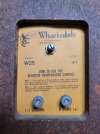
Background: I've had an old pair of Wharfedale W25 speakers laying around that I got from my dad many years ago along with a vintage Kenwood KR-710 stereo receiver, and finally decided to put them to use in the bedroom for TV sound (Plex for noise while falling asleep, e.g. old Mythbusters episodes). Already a big improvement over the tiny TV speakers, it finally has some bass.

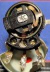
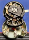
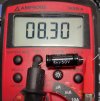
Problem: On one of the speakers, the tweeter completely cuts out when I turn the "acoustic compensator control" clockwise past about 1/4 up from minimum. On the other speaker it seems to work, where turning the dial seems to move the crossover frequency up and down, or at least changes the bias of treble and bass. Below is a picture of the crossover circuit, and while it's not labeled I could find from some forum searching that the cap is 6uF 50V non-polar (though one poster kept calling it 6mF). I can't find anything about the potentiometer, or if it even is one. I didn't want to start de-soldering anything because it technically works for now, and I'd like to keep using it until I have replacement parts ready. I measured resistance across the outer two legs of the dial component (in-situ, speakers disconnected) with my multimeter and it started at 0.8ohm and then slowly decayed down to 0.4ohm after a minute or two, with moving the dial having no effect. The capacitor leg to the blue wire leg seems to flutter all over the place, at full counter-clockwise position it was around 15ohm, then somewhere in the middle it stabilized at 9ohm, a little higher it sent to 30ohm but then got all jumpy, then at max it was basically open loop, but just back from max awas 5ohm. I then measured the center (blue wire) leg to the other (positive terminal) leg and it seems to closely match the resistance as between the center and left leg. I'm at a loss as to what this component really is. I'm a mechanical engineer by training and trade, electronics is just a small side hobby and I'm comfortable with a soldering iron but not at surface mount sizes.
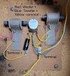
Can someone point me to what this is, and if it's something I can find a replacement for? Also, I guess, is it worth replacing the cap at the same time? I'd really like to avoid taking these apart more times than necessary because the drivers are just screwed into wood and every time they come out I feel like I'm damaging them more - plus dealing with the fiberglass insulation packed into the cabinets is irritating.
edit: title changed to Solved


Problem: On one of the speakers, the tweeter completely cuts out when I turn the "acoustic compensator control" clockwise past about 1/4 up from minimum. On the other speaker it seems to work, where turning the dial seems to move the crossover frequency up and down, or at least changes the bias of treble and bass. Below is a picture of the crossover circuit, and while it's not labeled I could find from some forum searching that the cap is 6uF 50V non-polar (though one poster kept calling it 6mF). I can't find anything about the potentiometer, or if it even is one. I didn't want to start de-soldering anything because it technically works for now, and I'd like to keep using it until I have replacement parts ready. I measured resistance across the outer two legs of the dial component (in-situ, speakers disconnected) with my multimeter and it started at 0.8ohm and then slowly decayed down to 0.4ohm after a minute or two, with moving the dial having no effect. The capacitor leg to the blue wire leg seems to flutter all over the place, at full counter-clockwise position it was around 15ohm, then somewhere in the middle it stabilized at 9ohm, a little higher it sent to 30ohm but then got all jumpy, then at max it was basically open loop, but just back from max awas 5ohm. I then measured the center (blue wire) leg to the other (positive terminal) leg and it seems to closely match the resistance as between the center and left leg. I'm at a loss as to what this component really is. I'm a mechanical engineer by training and trade, electronics is just a small side hobby and I'm comfortable with a soldering iron but not at surface mount sizes.

Can someone point me to what this is, and if it's something I can find a replacement for? Also, I guess, is it worth replacing the cap at the same time? I'd really like to avoid taking these apart more times than necessary because the drivers are just screwed into wood and every time they come out I feel like I'm damaging them more - plus dealing with the fiberglass insulation packed into the cabinets is irritating.
edit: title changed to Solved
Last edited:
