• WANTED: Happy members who like to discuss audio and other topics related to our interest. Desire to learn and share knowledge of science required. There are many reviews of audio hardware and expert members to help answer your questions. Click here to have your audio equipment measured for free!

Passive Filters to change headphones sound? PLEASE ENLIGHTEN ME!

Fraxo

Active Member
Joined
Jan 1, 2022
Messages
100
Likes
27
So I stumble upon this guy - modified the DT1990 and somehow created a Passive Filter to reduce the "8k" peak.
He mentioned @solderdude as well so I read a few posts here from years ago - yet my question remains (since no one addressed it):

I was wondering, how do you choose components THAT accurately impede current, in only specific frequency ranges and how does it work electronically? I mean, I understand that a capacitor could be used as a HP filter and an inductor - LP, but the guy in the vid mentioned that there's "a gap in the middle" where the chosen component only impede a certain range \ peak.

I would be highly appreciative if someone could break down the relationship between components in simple terms, to understand how they affect the incoming current SO specifically.

1) Is it difficult to achieve \ calculate for such narrow changes and how is it done properly?
2) What scientifically happens to the current out of the Amp and before it gets to the driver to be able to impede it so specifically rather than a common wider range?

Would love to play around with such DIY filters for learning purposes.

Thanks!


Last edited:

staticV3

Master Contributor
Joined
Aug 29, 2019
Messages
7,985
Likes
12,819
Cross over design for speakers might be a good place to start learning about this, since the concept is the same as Solderdude's filters.

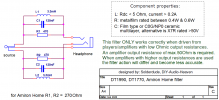
Here are the specifics of Solderdude's passive filter for the DT1990:
dt1990-filter-schematic-c.png
source

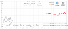
Here is the frequency response of just the filter on a GRAS 43AG:
graph (3).png
As you can see, the filter is actually not that precise. 7.8k is targeted, but the filter "bleeds" down to 3k.
That's just the nature of the beast. More precise analog filters quickly become complicated, expensive, and impractically large in size.
 
Last edited:
OP
Fraxo

Fraxo

Active Member
Joined
Jan 1, 2022
Messages
100
Likes
27
Here are the specifics of Solderdude's passive filter for the DT1990:
View attachment 243077
source

Can't say I immediately understand the relationship between the components and frequency response, I assume they have their electrical characteristics that correlate with it. Sorry about needing such simplifications in the explanations at this stage, I do my best to research and learn but I need the most simplified breakdown at this stage.

View attachment 243078
As you can see, the filter is actually not that precise. 7.8k is targeted, but the filter "bleeds" down to 3k.
That's just the nature of the beast. More precise analog filters quickly become complicated, expensive, and impractically large in size.

Thank you very much for this!
It does seem rather sporadic around the targeted range, which answers my question - how complicated it is to be accurate with it.
 
Last edited:

solderdude

Grand Contributor
Joined
Jul 21, 2018
Messages
16,051
Likes
36,426
Location
The Neitherlands
So I stumble upon this guy - modified the DT1990 and somehow created a Passive Filter to reduce the "8k" peak.
He mentioned @solderdude as well so I read a few posts here from years ago - yet my question remains (since no one addressed it):

I assume he used the filter I designed but possibly he did not build it correctly. Inductor choice, inductors being close to metal or magnets can change the actual response of an otherwise correctly designed filter. This is why the filters I make are all fully tested and verified to work as designed.

I was wondering, how do you choose components THAT accurately impede current, in only specific frequency ranges and how does it work electronically? I mean, I understand that a capacitor could be used as a HP filter and an inductor - LP, but the guy in the vid mentioned that there's "a gap in the middle" where the chosen component only impede a certain range \ peak.

It is done by using a filter design program and measurements using gear without a pinna and ear canal. This is important in this phase.
One can make filters with a different Q-factor by playing with the inductance/capacitance ratio and can determine the attenuation at the notch frequency by knowing the impedance at that frequency of the headphone + (range) of output resistance of an amplifier + the filter attenuation itself and this results in a specific resistor in parallel with the LC circuit.
There are tolerances to be dealt with and ohmic losses of the used inductor.

Here are 8 (DT1990) filters overlaid to get an idea of the tolerances of the used components (used by me).

prod tolerance 8 filters.jpg

This is what the filter actually does (measured attenuation)

1) Is it difficult to achieve \ calculate for such narrow changes and how is it done properly?

It is done properly with simulation software and by usage of comparative measurements to confirm filter action.
The range of filter frequencies, Q-factor and impedance of headphones is limited and does not allow complex filters and filters below a few kHz for practical reasons.

2) What scientifically happens to the current out of the Amp and before it gets to the driver to be able to impede it so specifically rather than a common wider range?

The amplifier sees a higher impedance so has to deliver less current at the filter frequency. Amps are voltage sources and amps usually perform better in higher impedances.
Of course, when the amp has an output resistance it will be in series with the filter and thus the attenuation at the filter frequency becomes less.
This can be an issue for lower impedance headphones. This is why I specify a max. output resistance of the amplifier per filter.

I can also design filters that are not source dependent but this requires an added series-filter on the amp side between output and ground. I can design/make this on request.

Would love to play around with such DIY filters for learning purposes.

You can do this and need a sound card, REW and some purpose made cables.

It does seem rather sporadic around the targeted range, which answers my question - how complicated it is to be accurate with it.

That is measurement error. The response is always the same (shown in the plots above) so is not sporadic. This is what Crinacle tested (I assume).
It is impossible to create complex filters as can be made digital as the practical values and impedances involved simply is not possible.
In most cases merely removing an annoying treble peak is enough.
 
Last edited:

MaxwellsEq

Major Contributor
Joined
Aug 18, 2020
Messages
1,746
Likes
2,634
.
i would be highly appreciative if someone could break down the relationship between components in simple terms, to understand how they affect the incoming current SO specifically.
Welcome to the world of filters and resonance circuits!

How to put this - when I did my electronic degree, this was something I had to study. There was no such thing as software simulation or word processors, so everything had to be worked out on paper. It was difficult, literally "under-graduate" level. So, you are simply not going to find a shortcut to understanding this material.

Things are easier now, because you can build filters in software like Ltspice and see what happens, make tweaks and see what changes the tweaks make. I did this, without Spice using real components in the laboratory. But there were only so many things I could try in the time, Spice allows an infinity of choices.

Doug Self's Small Signal book is a great place to start. https://www.amazon.co.uk/Small-Signal-Audio-Design-Douglas/dp/0367468956/ref=asc_df_0367468956/
 

isostasy

Senior Member
Joined
Oct 19, 2022
Messages
354
Likes
637
@solderdude I've always wondered what the formula is for your passive peaking filters in which the inductor, capacitor, and resistor are in parallel, like the DT1990 one linked above? They look unfamiliar to me and not much like the notch filter from Linkwitz.
 

solderdude

Grand Contributor
Joined
Jul 21, 2018
Messages
16,051
Likes
36,426
Location
The Neitherlands
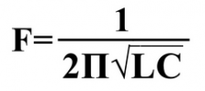
It is just a parallel filter in series with the driver.
Schermafdruk van 2022-11-13 22-05-39.png
 
OP
Fraxo

Fraxo

Active Member
Joined
Jan 1, 2022
Messages
100
Likes
27
I assume he used the filter I designed but possibly he did not build it correctly. Inductor choice, inductors being close to metal or magnets can change the actual response of an otherwise correctly designed filter. This is why the filters I make are all fully tested and verified to work as designed.


It is done by using a filter design program and measurements using gear without a pinna and ear canal. This is important in this phase.
One can make filters with a different Q-factor by playing with the inductance/capacitance ratio and can determine the attenuation at the notch frequency by knowing the impedance at that frequency of the headphone + (range) of output resistance of an amplifier + the filter attenuation itself and this results in a specific resistor in parallel with the LC circuit.
There are tolerances to be dealt with and ohmic losses of the used inductor.

Here are 8 (DT1990) filters overlaid to get an idea of the tolerances of the used components (used by me).

View attachment 243153
This is what the filter actually does (measured attenuation)


It is done properly with simulation software and by usage of comparative measurements to confirm filter action.
The range of filter frequencies, Q-factor and impedance of headphones is limited and does not allow complex filters and filters below a few kHz for practical reasons.


The amplifier sees a higher impedance so has to deliver less current at the filter frequency. Amps are voltage sources and amps usually perform better in higher impedances.
Of course, when the amp has an output resistance it will be in series with the filter and thus the attenuation at the filter frequency becomes less.
This can be an issue for lower impedance headphones. This is why I specify a max. output resistance of the amplifier per filter.

I can also design filters that are not source dependent but this requires an added series-filter on the amp side between output and ground. I can design/make this on request.


You can do this and need a sound card, REW and some purpose made cables.


That is measurement error. The response is always the same (shown in the plots above) so is not sporadic. This is what Crinacle tested (I assume).
It is impossible to create complex filters as can be made digital as the practical values and impedances involved simply is not possible.
In most cases merely removing an annoying treble peak is enough.

This is beautiful... Such dedication for this, and explaining it so well, I highly appreciate your response and great work!

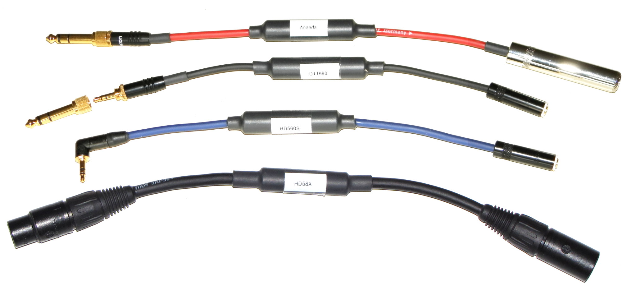
Another question that came to mind after reading this: so it means that each filter has to be designed exactly for the specific model intended right? Also how small could those filters possibly be, are they limited by overheating and could they come at a cable form? Would love to see your selection of filters.

I admire your work my friend.
 

solderdude

Grand Contributor
Joined
Jul 21, 2018
Messages
16,051
Likes
36,426
Location
The Neitherlands
so it means that each filter has to be designed exactly for the specific model intended right?

yes.

Would love to see your selection of filters.


MaxwellsEq

Major Contributor
Joined
Aug 18, 2020
Messages
1,746
Likes
2,634
Wow, that's an amazing site! Thanks for the link.
 

L5730

Addicted to Fun and Learning
Joined
Oct 6, 2018
Messages
670
Likes
439
Location
East of England
Hi,

If I am not mistaken, this like seems to help explain what is going on

I am messing about in LTSpice and have manged to plot the ~10kHz resonance cut filter that is often used in Solderdude's suggested filter designs for headphones.

In a parallel filter (like in Solderdude's examples), Resonance of the combination of Inductor and Capacitor causes a high impedance at that frequency - in other words blocking that frequency.

The value of the parallel resistor makes the cut higher for higher resistance.

I suppose the weakness of these passive filters is that as they come down to lower frequencies they'll obviously affect a wide-ish band. How tough is it to make them narrower/more selective?
Also, one can play with fictitious value all one wants in software, but when it comes to the real world, those values might not even exist and if they do, they may not be suitable for other reasons (eg. power handling).

I'm an utter n00b in electronics, in case that isn't obvious ;)
 
Top Bottom