jmf11
Active Member
*** This post is a duplicate from https://www.diyaudio.com/community/...-in-i2c-controlled-integrated-dsp-amp.398823/ ****
Even if it is an "old" project (https://www.diyaudio.com/community/...-controlled-integrated-dsp-amp-tas3251.325826), I create a new thread as the project goes fully open source along the lines of a Creative Commons Attribution-ShareAlike 4.0 International (CC BY-SA 4.0) licence.
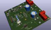
The NeatAmp is working since 2020. All elements, including the KiCAD files (v5) are now accessible in https://github.com/jmf13/NeatAmpTAS3251/tree/master in an open source hardware spirit along the lines of a Creative Commons Attribution-ShareAlike 4.0 International (CC BY-SA 4.0) licence.
As far as I know, there are not so many (no?) equivalent for digital input + DSP + this level of power.
The purpose of the project is to design an "amplification brick" for:
") . The quality shall be above the common offer around class D DIYT amps, where often design cuts the corners and needs retrofitting and "tuning" to have target performance. The neat amp uses Wüth coils, Elna Carafine on analog audio path, MKP... The TAS3251 datasheet performance is expected to be achieved in that design.
. The quality shall be above the common offer around class D DIYT amps, where often design cuts the corners and needs retrofitting and "tuning" to have target performance. The neat amp uses Wüth coils, Elna Carafine on analog audio path, MKP... The TAS3251 datasheet performance is expected to be achieved in that design.
A key idea is modularity. The amplification module shall easily interface with generic, open (manufacturer independant) and well spread protocols:
As much as possible the design of the "brick" shall not enforce usage options. I should, as far as possible, let the end user choose how he wants to use the amplification chip. This is a key difference with the ready made amps, where the cheap price comes with an heavy lack of flexibility.
The Open Source Hardware License and making KiCAD files available allows flexibility for the tuning of some key components (like output selfs and caps...), or usage.
The final system is cost competive with the latest Hypex fusion plates DIYclassd.com. 300€ for 2x125W + DSP + Power supply. Is it achievable to have a similar thing for 100€ ?
Last, It should be possible to build from PCB by the hobbyist, with achievable SMD soldering. This is to ensure that even if no manufacturing, the design could be useful to hobbyists.
The board has differenet possible use cases:
There is also an I2C 256K EEprom for parameters and DSP configurations storage (or other features).
STM32 uC programming can be done either in C, or Arduino style.
The discussion about the project can be found here [design log] Neat 2x170W I2S in, I2C controlled, integrated DSP amp (TAS3251)
To define the configuration of the TI TAS3251, usage of TI application PurePath console (PPC3) with the TAS3251 module is expected. When I started the project, TI was easily granting access to those applications. The Datasheets contain a lot of information on the registers and the configuration, but it seems that not all was documented.
Other important ressources:
TAS3251
NeatAmp Wiki
AIM65/NeatAMP-Test-Dev-software
Even if it is an "old" project (https://www.diyaudio.com/community/...-controlled-integrated-dsp-amp-tas3251.325826), I create a new thread as the project goes fully open source along the lines of a Creative Commons Attribution-ShareAlike 4.0 International (CC BY-SA 4.0) licence.
The NeatAmp is working since 2020. All elements, including the KiCAD files (v5) are now accessible in https://github.com/jmf13/NeatAmpTAS3251/tree/master in an open source hardware spirit along the lines of a Creative Commons Attribution-ShareAlike 4.0 International (CC BY-SA 4.0) licence.
As far as I know, there are not so many (no?) equivalent for digital input + DSP + this level of power.
The purpose of the project is to design an "amplification brick" for:
- Active speakers with DSP usage,
- digital centered audio systems, like systems based on Raspberry Pi, or PC music servers relying on digitalized music files, micro-controllers (uC) have also rich audio features very suitable for audio projects. Target applications are classic stereo systems, but more specifically multi channel active speakers, for which there are less easy to implement options for the hobbyist.
. The quality shall be above the common offer around class D DIYT amps, where often design cuts the corners and needs retrofitting and "tuning" to have target performance. The neat amp uses Wüth coils, Elna Carafine on analog audio path, MKP... The TAS3251 datasheet performance is expected to be achieved in that design.A key idea is modularity. The amplification module shall easily interface with generic, open (manufacturer independant) and well spread protocols:
- I2S for the audio streams (reference interface since the beginning)
- I2C for the control of the device (propocol that we can find in any uC
As much as possible the design of the "brick" shall not enforce usage options. I should, as far as possible, let the end user choose how he wants to use the amplification chip. This is a key difference with the ready made amps, where the cheap price comes with an heavy lack of flexibility.
The Open Source Hardware License and making KiCAD files available allows flexibility for the tuning of some key components (like output selfs and caps...), or usage.
The final system is cost competive with the latest Hypex fusion plates DIYclassd.com. 300€ for 2x125W + DSP + Power supply. Is it achievable to have a similar thing for 100€ ?
Last, It should be possible to build from PCB by the hobbyist, with achievable SMD soldering. This is to ensure that even if no manufacturing, the design could be useful to hobbyists.
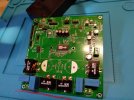
The board has differenet possible use cases:
- The board embeds a stm32 uC that allows the board to operate stand alone, for example behind a simple USB to I2S board. The onboard uC controls the TAS3251, loads the DSP parameters, controls the volume,
- The board is the slave of a Rpi, controlled by RPi I2C and fed by I2S (possible but not implemented yet)
There is also an I2C 256K EEprom for parameters and DSP configurations storage (or other features).
STM32 uC programming can be done either in C, or Arduino style.
The discussion about the project can be found here [design log] Neat 2x170W I2S in, I2C controlled, integrated DSP amp (TAS3251)
To define the configuration of the TI TAS3251, usage of TI application PurePath console (PPC3) with the TAS3251 module is expected. When I started the project, TI was easily granting access to those applications. The Datasheets contain a lot of information on the registers and the configuration, but it seems that not all was documented.
Other important ressources:
TAS3251
NeatAmp Wiki
AIM65/NeatAMP-Test-Dev-software