• WANTED: Happy members who like to discuss audio and other topics related to our interest. Desire to learn and share knowledge of science required. There are many reviews of audio hardware and expert members to help answer your questions. Click here to have your audio equipment measured for free!

NC252MP (class D) vs. A250W4R (classAB) burst measurements into 4ohm//2.2uF load

Nope. It is you that is not understanding the topic or that measurement. First, show the link to the reviews on stereophile and not just the graphs. Here is the link: https://www.stereophile.com/content/primaluna-dialogue-seven-power-amplifier-measurements

Right there, JA explains what is going on which is what I explained:

"In 8 ohm impedance feeding an 8 ohm load transfers more power to the load than would a greater or smaller impedance. However, there is a price to be paid: because loudspeaker impedances vary considerably with frequency, high output impedances result in significant modification of the amplifier's frequency response, due to the Ohm's Law interaction between the amplifier and loudspeaker impedances. This is illustrated by the gray trace in fig.1, which shows the DiaLogue Seven's frequency response from the 4 ohm tap in ultralinear mode into Stereophile's standard simulated loudspeaker."

As I already explained, the response changes due to high impedance of the amplifier, in this case 8 ohm. This clearly shows up in response differences of 4 vs 8 ohm. Ohm's law works there and as JA says, it works exactly the same in a varying impedance load. At any point in that varying load, you can use the simple Ohm's law to compute the impact. No new insight is gained other than application of Ohm's law to resistive vs reactive load. This is why i said the impact on your actual speaker will be different. Best to avoid these amps with high impedance. But if you can't avoid it, then use acoustic measurements to deal with it. Nothing is gained by looking at at that simulated line. The only insight was 8 ohm impedance of the amplifier. Period.
Actually, the author’s explanation applies to only one parameter - the swept frequency response. This logic does not apply in any way to, say, a Class D circuit whose oscillation frequency might be altered by a reactive load, leading to aliased in-band noise and/or spurious. The latter nonlinear effect is what the OP discovered originally, not some bump in the linear swept frequency response. Yes, the load was extreme, unrealistic,… add your favorite verb to describe it. But for me, it shined a spotlight on a potentially unique characteristic of Class D’s. Maybe purely academic - but also maybe something for Class D designers to consider.
 
Examples of class D (LC out of FB) amplifier's FR modulated by complex load below 20kHz (yes it was NOT the topic of this thread, it is off-topic):

A07_FR_4ohm_x_JBL.png


AIYIMA_JBL1controlPro.png


AIYIMA_dummyload.png


What else would one expect from this???
LC_outimp.png


It is all trivial response of LC loaded with complex impedance. In case of testing with resitor 4 - 8 ohm only the only thing changed is the 2nd order LP filter LC damping factor. Sorry but such basic info should be as clear as ABC.

LCfilter_damping.png
 
Last edited:
This logic does not apply in any way to, say, a Class D circuit whose oscillation frequency might be altered by a reactive load, leading to aliased in-band noise and/or spurious.

Exactly.
 
Again, you don't understand. Class D amplifiers with load dependency have variable output impedance that is frequency dependent. My resistive tests shows this very clearly. You can compute the impedance vs frequency from my measurements. Once there, the exact same thing will apply to a reactive load. To the extent the impedance of a class D amp is very low at low frequencies, there is no impact with resistive load or reactive one at lower frequencies. So there is nothing to see "in band." The issue is limited to high frequencies which once again, my test shows.
I do understand Amir.

Yes, your data does show an out of band deviation. It doesn't show how it behaves with a reactive load in band.
My data demonstrates your assumption that purely resistive loads fully describes the behaviour of amplifiers to be wrong. I have no need to argue with you about it, the facts are in the graphs. It's your understanding that is clearly wrong.

This isn't about class d amps.
 
Last edited:
“The longer I test test the Hypex NC252MP, the more my initial passion for this class D amplifier is fading away and the more my scepticism to class D is growing.”

Is this still valid after days and weeks discussion?
 
I’m not “asking” for anything. You’ve gotten very defensive over your present test methods, which was not my intent at all. I’m simply pointing out what any amplifier circuit designer knows very well - namely, amplifiers (and other active circuits) can and will do strange things with reactive loads.

Yes. I'm a bit shocked to see this being argued about TBH.
 
I do understand Amir.

Yes, your data does show an out of band deviation. It doesn't show how it behaves with a reactive load in band.
My data demonstrates your assumption that purely resistive loads fully describes the behaviour of amplifiers to be wrong. I have no need to argue with you about it, the facts are in the graphs. It's your understanding that is clearly wrong.

This isn't about class d amps.
What is shown is EXACTLY what one expects knowing the source impedance. If you have that, the frequency response deviations are trivially predictable for any practical load. There's no mystery, no "new knowledge" to be gained. The amp is not "going crazy." Voltage dividers, all stuff understood for more than a century.
 
Examples of class D (LC out of FB) amplifier's FR modulated by complex load below 20kHz (yes it was NOT the topic of this thread, it is off-topic):

View attachment 276986


View attachment 276987


View attachment 276988


What else would one expect from this???
View attachment 276990

It is all trivial response of LC loaded with complex impedance. In case of testing with resitor 4 - 8 ohm only the only thing changed is the 2nd order LP filter LC damping factor. Sorry but such basic info should be as clear as ABC.

View attachment 276995

Whilst I do not agree with your testing in the OP, this data here demonstrates quite clearly that purely resistive loads do not characterise a class d amplifier response.
 
What is shown is EXACTLY what one expects knowing the source impedance. If you have that, the frequency response deviations are trivially predictable for any practical load. There's no mystery, no "new knowledge" to be gained. The amp is not "going crazy." Voltage dividers, all stuff understood for more than a century.

Excuse my use of over zealous language, but you are missing the point.

I am not saying there is anything new going here. This is obvious knowledge to EEs (or should be). However, how many readers understand the subjects that deeply? Do we know any of the amps output impedance wrt frequency?

What Amir is claiming, is plain wrong. A graph of a purely resistive load does not tell you how the amp will behave. Just go to stereophile to see dozens of examples of how amps behave differently with reactive loads.
 
Last edited:
What Amir is claiming, is plain wrong. A graph of a purely resistive load does not tell you how the amp will behave.
Ooh, ooh, a straw man!

Is it intentional or do you not actually understand how source impedance is derived?
 
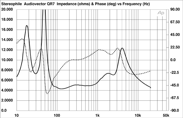
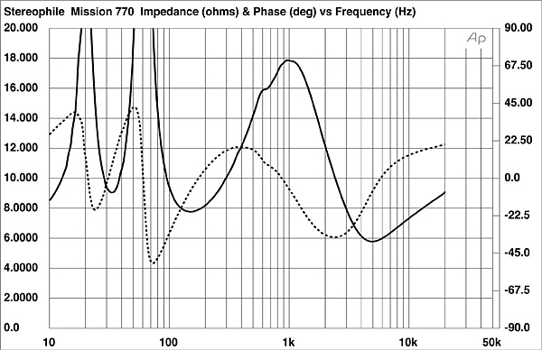
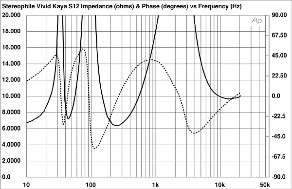
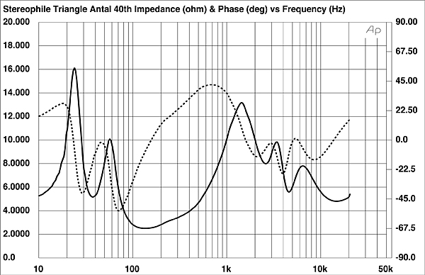
As often I think we are overcomplicating things. Personally I would love to see the amplifier measurements on a typical loudspeaker load with the the common 3 impedance peaks (2 in the bass and one at the crossover to the tweeter) and corresponding phase deviations, just from random picking of some recent Stereophile reviews:

922TA40fig1.jpg


822AQR7fig1.jpg


1022M770fig1.jpg


322vivd.VivS12fig1.jpg


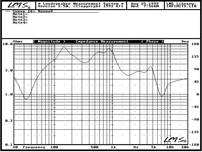
I would choose one of such with a relatively high variation both in amplitude as well in phase, if an amp behaves well with such it will perform also well with the biggest part of the loudspeakers in the market. Of course there will still be few exceptions like the old Infinity Kappa 9 going in the bass to 0.8 Ohm but luckily such have no real market significance nowadays:

Kappa9Impedance.jpg.340a528e36b90ff2b94f383547346fb2.jpg
 
Ooh, ooh, a straw man!

Is it intentional or do you not actually understand how source impedance is derived?
There is no straw man. The derivation is unimportant. This is about testing methodologies and the information presented @pma pma is right in this respect that purely resistive loads do not characterise amplifier performance adequately. Even the limited number of examples shown in this thread show you cannot infer one from the other.
 
As often I think we are overcomplicating things. Personally I would love to see the amplifier measurements on a typical loudspeaker load with the the common 3 impedance peaks (2 in the bass and one at the crossover to the tweeter) and corresponding phase deviations, just from random picking of some recent Stereophile reviews:

922TA40fig1.jpg


822AQR7fig1.jpg


1022M770fig1.jpg


322vivd.VivS12fig1.jpg


I would choose one of such with a relatively high variation both in amplitude as well in phase, if an amp behaves well with such it will perform also well with the biggest part of the loudspeakers in the market. Of course there will still be few exceptions like the old Infinity Kappa 9 going in the bass to 0.8 Ohm but luckily such have no real market significance nowadays:

Kappa9Impedance.jpg.340a528e36b90ff2b94f383547346fb2.jpg

I agree. It's about giving an indication of the propensity for an amplifier to change its performance (therefore sound) with real world speakers. The stereophile data, even with just one reactive load, provides this information. There are some amps I wouldn't touch because they clearly significantly change their sound depending on what speaker is attached.
 
The derivation is unimportant.
Where's the forehead-slap emoji on this keyboard?

Source impedance is EVERYTHING here. If you actually don't get that, it's time for you to review some very basic electrical concepts.
 
Where's the forehead-slap emoji on this keyboard?

Source impedance is EVERYTHING here. If you actually don't get that, it's time for you to review some very basic electrical concepts.
Yeah, you really are missing the point.

So do you think it's clear to lay readers just from looking at the 4 and 8 ohm resistive load responses in the graph below, that the amp might change its response to something like the black line when connected to a real speaker?
1209PD7fig01.jpg

Does this amp only vary by the 0.3dB indicated by the difference between 4 and 8 ohms resistive lines?

1017DagProfig01.jpg


Then what about how an amp behaves WRT power and heat dissipation with reactive loads?
 
Last edited:
Yeah, you really are missing the point.

So do you think it's clear to lay readers just from looking at the 4 and 8 ohm resistive load responses in the graph below, that the amp might change its response to something like the black line when connected to a real speaker?
So we've moved on to the "no true Scotsman" argument.

If the concept of voltage dividers is unclear to you, I'd strongly suggest you bone up on the basics.
 
Indiscriminate skepticism is no more useful than blind faith.

I don't mean to sound harsh - it's just that without a heuristic approach, anything and everything can seem equally plausible and we can potentially ask endless questions without ever figuring out which questions are most important to ask given the limited time and resources we have, and the knowledge that's already been established.
Well...I'm not exactly skeptical. Obviously the class D amps are working well for the vast majority. If anything I'd like to see more actual information on exotic speaker loads. I'm perfectly willing to believe that they may not be a problem.
 
So we've moved on to the "no true Scotsman" argument.

If the concept of voltage dividers is unclear to you, I'd strongly suggest you bone up on the basics.

You need to stop the "you dont understand" nonsense.

Your, and Amirs implication Is that a 4 and 8 ohm resistive plot offers all you need to know. Possibly that the simple difference in level between the two provides a clear indication of what an amp will behave like with a reactive load? I don't really know.

Well let's take PMA data above. If we look at the 4 and 8 ohm plots at 7kHz they only have a fractional difference in level.

LCfilter_damping(1).png


And yet when connected to a real speaker we see a peak of 0.7dB
A07_FR_4ohm_x_JBL.png


Whilst of course this is the result of the actual speaker impedance and amp output impedance, how would a lay reader interpret the purely resistive lines to ascertain what might happen with a real speaker?

Are you suggesting amp output impedance remains constant with frequency?
 
Last edited:
You need to stop the "you dont understand" nonsense.

Your, and Amirs implication Is that a 4 and 8 ohm resistive plot offers all you need to know.
And voila, you inadvertently proved that indeed you don't understand. Last time I will suggest this before giving up that you have any actual curiosity: bone up on basic electricity, with particular attention to voltage dividers. If you can't or won't do that, you really have no business trying to interpret electrical data.

edit: I'd add in Thevenin. This is very basic stuff that will greatly enrich your understanding.
 
I know this continued discussion is frustrating for some. Especially given the brilliant and essentially "free to me" work from @amirm and others who have the equipment and patience to run tests on real world products without any reward from advertisers and manufactures. In my experience of HiFi I've never been so blessed with excellent information and guidance.

I have a mental model of a Class D (which is not the same as the classic block diagrams) of a black box that provides gain in the audio frequency bands superimposed with an RF device producing Radio Frequency signals which cannot be played by our speakers and which we cannot hear and which is mostly blocked from reaching our speakers by the output filter.

What this thread seems to be about is - perturbations to the RF amplifier - 1) whether a real world device can cause an interaction and 2) whether such an interaction perturbs the RF device, 3) how would we sensibly test and present this.

What is perhaps relevant is how many people are really satisfied with their Class D amps in the real world. Obviously, the vast majority of purchasers can not measure how well the amp works, but if there are real world perturbations to the RF device that folds artefacts such as noise and distortion back into the audio bands, we're not encountering complaints...
 
Back
Top Bottom