I would recommend looking at this https://github.com/marcoevang/camilladsp-setrate
I don't use it myself as my input is always the same sample rate, but there is a thread on DIYaudio https://www.diyaudio.com/community/threads/sample-rate-switcher-for-camilladsp.403054/
This would allow you to turn off the resampling in PiCorePlayer and just have CDSP's async resampling.
However, I don't think this will make any real difference. Upsampling from one audio rate to a higher rate results in a mathematically identical signal if done properly. It just reduces the load on your PiCorePlayer.
Personally I would run everything on a single Pi, but you would need to use a loopback device.
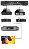
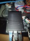
") The PI's get passiv Cooling and be Silent.
The PI's get passiv Cooling and be Silent.")

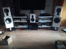
 so no thats to expensive and not powerfull / flexible enough for my Project. 7.2 full aktiv System.