Highest frequency arrives first and the rest is aligned with that as it should.Hi, Why do you like the latter better?
-
Welcome to ASR. There are many reviews of audio hardware and expert members to help answer your questions. Click here to have your audio equipment measured for free!
You are using an out of date browser. It may not display this or other websites correctly.
You should upgrade or use an alternative browser.
You should upgrade or use an alternative browser.
Influence of pressure-field, diffuse-field, and free-field microphones on microphone orientation
- Thread starter Keith_W
- Start date
WIth all due respect, I have been following your progress and your deserved joy in measuring THD+N beyond -130dB by means of noise cross correlation elsewhere in this forum and I believe no improvement is too little in this hobby.other than the microscopic differences at the very top end
Brilliant, thanks!EXTENDING THE LOW FREQUENCY ACOUSTIC CENTRE CONCEPT TO DIRECTIONAL LOUDSPEAKERS | I
Hmmm...I'd say every frequency coming out of the high frequency driver arrives at the same absolute time....albeit with varying degrees of phase rotation between them.Highest frequency arrives first and the rest is aligned with that as it should.
Ime, whether 20kHz is exactly at zero degrees, and the rest of the spectrum's phase is relative to that point, matters very little.
(if being at zero degrees is what you were saying is better)
What does matter to me, is how relatively flat and smooth the high frequency driver's mag and phase are, and how well it's phase trace overlays the section below it.
And also that the 20kHz tail is reasonably close to zero, but only if there is flat response out to at least 20kHz. If not phase should not be zero at 20kHz, it should reflect the mag roll-off.
Assuming flat mag to 20kHz, any phase value for 20kHz that's within say +/- 30 degrees is essentially equal, ime.
With 48kHz sampling, I can't measure better than that. It's by pure measurement luck, when 0 degrees lines up exactly with a sample.
Remove IR delay from measurement before extracting excess phase.Hmmm...I'd say every frequency coming out of the high frequency driver arrives at the same absolute time....albeit with varying degrees of phase rotation between them.
Ime, whether 20kHz is exactly at zero degrees, and the rest of the spectrum's phase is relative to that point, matters very little.
(if being at zero degrees is what you were saying is better)
What does matter to me, is how relatively flat and smooth the high frequency driver's mag and phase are, and how well it's phase trace overlays the section below it.
And also that the 20kHz tail is reasonably close to zero, but only if there is flat response out to at least 20kHz. If not phase should not be zero at 20kHz, it should reflect the mag roll-off.
Assuming flat mag to 20kHz, any phase value for 20kHz that's within say +/- 30 degrees is essentially equal, ime.
With 48kHz sampling, I can't measure better than that. It's by pure measurement luck, when 0 degrees lines up exactly with a sample.
Sure, of course. I take removing constant delay as a necessary given, for assessing measurements and applying filters.Remove IR delay from measurement before extracting excess phase.
So i can't see how that is relevant to the points I raised about phase not needing to be overly/exactly precise at 20kHz?
Or whether we even want phase at 20kHz to be at zero, if the 20kHz magnitude region isn't flat?
Neither I nor you can hear above 16kHz. What matters very little and what matters a lot is a bit out of context here. But if you are arguing just for the sake of it, it's EXCESS PHASE I am dealing with in the graphs. You do not correct phase directly! Remove all min phase from the response first which covers all that you try to explain on mag response deviations, etc. then fix what you can in what's left.Sure, of course. I take removing constant delay as a necessary given, for assessing measurements and applying filters.
So i can't see how that is relevant to the points I raised about phase not needing to be overly/exactly precise at 20kHz?
Or whether we even want phase at 20kHz to be at zero, if the 20kHz magnitude region isn't flat?
Last edited:
Neither I nor you can hear above 16kHz. What matters very little and what matters a lot is a bit out of context here. But if you are arguing just for the sake of it, it's EXCESS PHASE I am dealing with in the graphs. You do not correct phase directly! Remove all min phase from the response first which covers all that you try to explain on mag response deviations, etc. then fix what you can in what's left.
Still hear above16k? , I wish Lol....14k is my reality. And no, don't mean to be arguing for sake of it...that's good for nothing imo
My previous comments were meant to simply be saying I know of no reason to discern, or care, which of the two graphs posted in #35 might be better.
The only difference I can see between them is how the phase trace terminates at 20kHz??? Is there more?
I don't use FIR for correcting existing speakers. I use it on each driver section separately, making min phase corrections first, then adding complementary lin phase crossovers.
I've found FIR generators, that have excellent auto target-matching capability at the driver level, make this very easy. Minimum phase corrections and lin phase
Net result is there is no excess phase to deal with, or phase corrections needed, for the full speaker. IOW, flat mag and phase across the spectrum.
Having done done this myriads of times for many multi-ways, I've learned I'd much rather have perfectly flat mag and phase through the HF driver and VHF driver xover, than a perfect phase tail to 20K for the VHF.
I've learned to ignore where exactly 20kHz phase lands, as long as it's within reason. That's what I was trying to say earlier.
Last edited:
ernestcarl
Major Contributor
Neither I nor you can hear above 16kHz. What matters very little and what matters a lot is a bit out of context here. But if you are arguing just for the sake of it, it's EXCESS PHASE I am dealing with in the graphs. You do not correct phase directly! Remove all min phase from the response first which covers all that you try to explain on mag response deviations, etc. then fix what you can in what's left.
Do you have a nearfield measurement to show your own mic's differences better?
It seems the minimum phase calibration file I loaded (which was created some time ago) isn't quite correct. So I generated a new one:
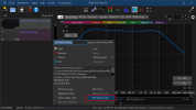
Anyhow, with my own UMIK-1 microphone, there's an appreciable difference between loaded calibration data with the HF shifting a bit more so -- but the difference is still not what I would call producing "significant" phase shifts when IR centering is adjusted to compensate/match with the mic correction curve that includes the "minimum phase" info:
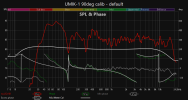
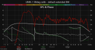
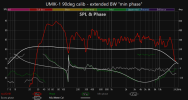
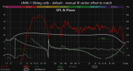
Well, it does not seem to "hurt" to include that column of phase information in... so I don't really care either way. If it helps you sleep at night, fine -- but, I would avoid telling people it's a missing critical piece of information necessary to achieve audibly better system optimization results.
Last edited:
True that and I agree but then since I don't hear beyond 15-16kHz, why bother with mic cal file at allDo you have a nearfield measurement to show your own mic's differences better?
It seems the minimum phase calibration file I loaded (which was created some time ago) isn't quite correct. So I generated a new one:
View attachment 387195
Anyhow, with my own UMIK-1 microphone, there's an appreciable difference between loaded calibration data with the HF shifting a bit more so -- but the difference is still not what I would call producing "significant" phase shifts when IR centering is adjusted to compensate/match with the mic correction curve that includes the "minimum phase" info:
View attachment 387196 View attachment 387197 View attachment 387198 View attachment 387199
View attachment 387217
Well, it does not seem to "hurt" to include that column of phase information in... so I don't really care either way. If it helps you sleep at night, fine -- but, I would avoid telling people it's a missing critical piece of information necessary to achieve audibly better system optimization results.
I would double check that, mine goes away at 13800 but comes back momentarily at 1600014k is my reality
Correcting the minimum phase response is more critical than whether the correction filters used are minimum or linear phase as that is the only truly invertable part of the steady state response. Phase correction by FIR filters is useful, but it must be used with parsimony due to very long left side tails in the filter’s impulse response. This has significant latency and possibility to hear a pre‐echo due to time‐masking drawbacks. Lately, I don't correct phase beyond crossover linearization and fixing minor excess phase differences between the left and right speakers.making min phase corrections first
Correcting the minimum phase response is more critical than whether the correction filters used are minimum or linear phase as that is the only truly invertable part of the steady state response. Phase correction by FIR filters is useful, but it must be used with parsimony due to very long left side tails in the filter’s impulse response. This has significant latency and possibility to hear a pre‐echo due to time‐masking drawbacks. Lately, I don't correct phase beyond crossover linearization and fixing minor excess phase differences between the left and right speakers.
I'm glad I don't have to mess with correcting existing loudspeakers. I look at that task like remodeling an old home and finding out what walls, floors and ceilings;
are out of level, not plumb, not square, not flat, etc. etc
It takes a better builder to remodel I think, than to build new construction...which is what I do with DIY multi-ways.
I have a simpler path, being able to assure all driver sections are trued before combining.
Ok, too much off-topic I think.
To make amends and get back to mics, and their orientations...here's a link with an interesting old Meyersound paper....
Similar threads
- Replies
- 17
- Views
- 2K
- Replies
- 3
- Views
- 908
- Replies
- 16
- Views
- 1K
- Replies
- 44
- Views
- 4K