• WANTED: Happy members who like to discuss audio and other topics related to our interest. Desire to learn and share knowledge of science required. There are many reviews of audio hardware and expert members to help answer your questions. Click here to have your audio equipment measured for free!

Homemade Passive Preamplifier

AudioLover

Member
Joined
Dec 7, 2020
Messages
13
Likes
11
Location
Hong Kong
Hello all! Just new to the forum and would like to share my first handmade passive preamp! In fact, before that I've also shared my work through several diy audio forums, but sadly just very few of them could understand the principles. Wish to meet those here!

Lots of fun to make it successfully amplifying and tuning sound quality in thick bass or accurate positioning
biggrin.png
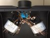
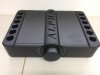
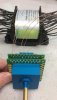
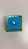
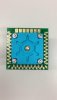
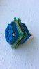
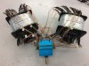
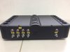
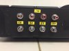
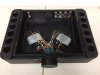
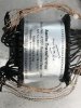
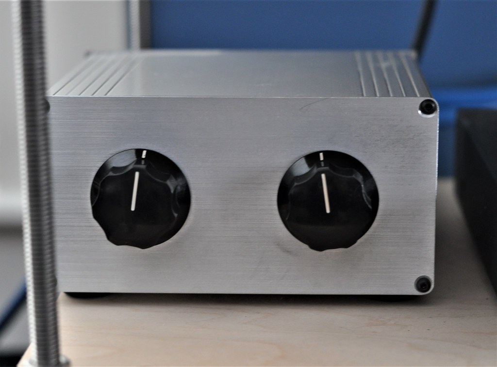
Attached below with some images about the attenuator, transformer, casework etc., you guys may also take a look at the schematic for the whole circuit. Those attenuator and transformer are handcrafted and manufactured from my hometown Hong Kong, which I really appreciate the sound quality and technology applied.

I am looking forward to discussing my work with all of you! Feel free to ask me anything about it.
500000033.gif.92511e2005a900cfb9bb836a01712b3a.gif
 

Attachments

  • Core2.jpeg
    Core2.jpeg
    134 KB · Views: 948
  • Top.jpeg
    Top.jpeg
    45.6 KB · Views: 997
  • Transformer and Switch.jpeg
    Transformer and Switch.jpeg
    63.8 KB · Views: 1,045
  • VR1.jpeg
    VR1.jpeg
    36.4 KB · Views: 646
  • VR2.jpeg
    VR2.jpeg
    39.6 KB · Views: 660
  • VR3.jpeg
    VR3.jpeg
    48.9 KB · Views: 716
  • VR4.jpeg
    VR4.jpeg
    141.1 KB · Views: 986
  • Back.jpeg
    Back.jpeg
    49.9 KB · Views: 737
  • Back2.jpeg
    Back2.jpeg
    89.1 KB · Views: 740
  • Core.jpeg
    Core.jpeg
    67.3 KB · Views: 1,380
  • Transformer-min.jpeg
    Transformer-min.jpeg
    888.5 KB · Views: 871
  • Schematic.pdf
    24 KB · Views: 301
Last edited:

mugbot

Active Member
Forum Donor
Joined
Jul 3, 2020
Messages
120
Likes
109
Location
Adelaide
Loving the casing, that's better looking than many mass produced amplifiers out there.
 
OP
AudioLover

AudioLover

Member
Joined
Dec 7, 2020
Messages
13
Likes
11
Location
Hong Kong
Loving the casing, that's better looking than many mass produced amplifiers out there.
Thanks and I love it too! But a little embarrassing to say that this was just bought from taobao LOL, so you may find out some similar or exactly the same casework from others which I've already saw that:facepalm:
 

mugbot

Active Member
Forum Donor
Joined
Jul 3, 2020
Messages
120
Likes
109
Location
Adelaide
Haha well at least it looks nice! Appreciate the honesty.
 

Blumlein 88

Grand Contributor
Forum Donor
Joined
Feb 23, 2016
Messages
20,765
Likes
37,619
So from the markings do I understand correctly you are using the transformer to get voltage gain?
 
OP
AudioLover

AudioLover

Member
Joined
Dec 7, 2020
Messages
13
Likes
11
Location
Hong Kong
So from the markings do I understand correctly you are using the transformer to get voltage gain?
Yes! Definitely! Here I used a 59 steps autotransformer for voltage amplifying. Magnetic force is induced throughout this C Core transformer, with 1X, 3X, 5X and 10X gain options, sound qualities could vary from sweet to thick bass to super thick...There is no need to use any power sources, meaning no active components or power line/supplies or wall plug are used, so no noise and distortion will be added to the passive preamp. Plus, a 59 steps mechanical volume switch is used(really not an electronic one!) which makes me feel concrete and great during tuning!
 

pozz

Слава Україні
Forum Donor
Editor
Joined
May 21, 2019
Messages
4,036
Likes
6,827
Where did you have the case made?

It copies the Aavik Acoustics U-380 integrated amplifier.
1607691632907.png

1607691613431.png
 

Matias

Master Contributor
Forum Donor
Joined
Jan 1, 2019
Messages
5,086
Likes
10,945
Location
São Paulo, Brazil
Brilliant case design stolen from Aavik, love it!
 
OP
AudioLover

AudioLover

Member
Joined
Dec 7, 2020
Messages
13
Likes
11
Location
Hong Kong
OP
AudioLover

AudioLover

Member
Joined
Dec 7, 2020
Messages
13
Likes
11
Location
Hong Kong
Brilliant case design stolen from Aavik, love it!
Not sure whether you know about taobao, I just bought the case for my diy work. Sooner I found either one of them copy the others(I don't dare to say which side as I've no evidence, but many of us will know:rolleyes:), that's why you'll see exactly the same casework from my work:facepalm:
 

GDK

Addicted to Fun and Learning
Forum Donor
Joined
Aug 8, 2020
Messages
561
Likes
1,549
Location
Toronto
Not sure whether you know about taobao, I just bought the case for my diy work. Sooner I found either one of them copy the others(I don't dare to say which side as I've no evidence, but many of us will know:rolleyes:), that's why you'll see exactly the same casework from my work:facepalm:
Don’t worry about it. It looks great and was an inspired choice for a case.
 

Blumlein 88

Grand Contributor
Forum Donor
Joined
Feb 23, 2016
Messages
20,765
Likes
37,619
Now I'm lazy so rather than work it out for myself I will ask.

What sort of input and output impedances do you get with the different gain settings? I know that will reflect back through the transformer and be dependent upon the impedance of the amp input. And have you done any measures of frequency response to see how the transformers perform at the various gain levels?
 

pozz

Слава Україні
Forum Donor
Editor
Joined
May 21, 2019
Messages
4,036
Likes
6,827
Check out my previous comment:
Aavik probably bought it from taobao too;)

Nice choice of case anyway.

One thing I'd say about your comments previously is that you'll be surprised about just how much distortion those transformers introduce if you care to measure the result.
 

AnalogSteph

Major Contributor
Joined
Nov 6, 2018
Messages
3,391
Likes
3,339
Location
.de
On the topic of surprises, resulting input and output impedances will have some of those in store as well. Hint: Impedance transformation goes with turns ratio squared... At 1:10, a normally harmless 200 ohm output impedance turns into 20 kOhms... that's much restricting cable length if nothing else.

In a nutshell, a passive preamp is avoiding small problems... while introducing much bigger ones.

Even the performance of transformers can be much improved by active circuitry. For example, for lowest distortion they have to be driven by a slightly negative source impedance to cancel out winding resistance - or at least, you want no more than a small fraction of nominal input impedance. And if you want a high-impedance input transformer with good CMRR, you can't load the thing down too much in terms of capacitance before ultrasonic peaking becomes an issue, so a buffer following tends to be a good idea.

Avoiding active circuitry at all costs is a sure sign of superstition rather than knowledge. I mean, something like the Topping Pre90 is maxing out Amir's Audio Precision System while being all active, what more do you want?
 
Last edited:

mhardy6647

Grand Contributor
Joined
Dec 12, 2019
Messages
11,403
Likes
24,722
Attenuation without doing damage to the signal is all about maintaining constant impedance (in my Neanderthal-level opinion, seasoned by anecdotal and empirical impedance). :)

I like the intention of the titular "preamp" in this thread -- I am in no position to pass judgment on the design/implementation, but it looks promising to me and I'd love to try one if the opportunity ever arose. :)

I use one of Dave Slagle's tapped transformers for volume control at my house (and FWIW) -- this one as conceived and built by "Redboy" of audiokarma, not me, I must confess. :rolleyes:

DSC_4219 (2) by Mark Hardy, on Flickr
(just to be clear -- the left knob is a 3-position source selector; the right knob is the stereo attenuator... unlabeled to keep the riff-raff away ;) )

http://www.intactaudio.com/

I think it is safe to say that Dave and his colleagues believe in inductive solutions to audio problems. :cool:
 
OP
AudioLover

AudioLover

Member
Joined
Dec 7, 2020
Messages
13
Likes
11
Location
Hong Kong
Now I'm lazy so rather than work it out for myself I will ask.

What sort of input and output impedances do you get with the different gain settings? I know that will reflect back through the transformer and be dependent upon the impedance of the amp input. And have you done any measures of frequency response to see how the transformers perform at the various gain levels?

I don't have the exact data about that. As I bought the attenuator and transformer from a Hong Kong manufacturer(introduce more later), who stated the minimum output impedance is 10k ohm. I think you may contact them for more information.

More about the attenuator and transformer I bought, are 59 steps autotransformers. According to the manufacturer, this 59 steps autotransformers perform a frequency response ranging from 20-20kHz with +/-3dB. However what I measured is actually ranging from 20-20kHz with +/-0.5dB with a 47kohm loading at 10X gain option, which is really impressive.

I am not familiar with the rules here, can I mention the name and website of the manufacturer so that you all could learn more about that?
 
Last edited:
OP
AudioLover

AudioLover

Member
Joined
Dec 7, 2020
Messages
13
Likes
11
Location
Hong Kong
Aavik probably bought it from taobao too;)

Nice choice of case anyway.

Thanks anyway:D

One thing I'd say about your comments previously is that you'll be surprised about just how much distortion those transformers introduce if you care to measure the result.

This is true. Somehow that's what I want as those distortions introduced by transformers is actually making sound sweeter. However distortions from solid-state amplifier make sound ear-piercing. This is the reason why McIntosh which is a solid-state amplifier, also adding a transformer at the output.
 
OP
AudioLover

AudioLover

Member
Joined
Dec 7, 2020
Messages
13
Likes
11
Location
Hong Kong
On the topic of surprises, resulting input and output impedances will have some of those in store as well. Hint: Impedance transformation goes with turns ratio squared... At 1:10, a normally harmless 200 ohm output impedance turns into 20 kOhms... that's much restricting cable length if nothing else.

May I firstly clarify that transformer impedance goes with turns ratio to 10 times as at 1:10, so a 200 ohm output impedance turns into in fact 2k ohm instead of 20k ohm. Output impedance in CD or network player is very low, so what you mentioned will not happen.
 
Top Bottom