• WANTED: Happy members who like to discuss audio and other topics related to our interest. Desire to learn and share knowledge of science required. There are many reviews of audio hardware and expert members to help answer your questions. Click here to have your audio equipment measured for free!

DSP Measurements and Rising Noise Floor

DWPress

Major Contributor
Forum Donor
Joined
May 30, 2018
Messages
1,023
Likes
1,473
Location
MI
I think Camilla only does PEQ/biquad and that's how those filters were created?

MiniDSP products have had sub/bass filter resolution problems for over a decade mostly because the hardware has limited processing power to resolve the quantity of filters needed and using biquads over PEQ is always recommend. For their hardware that can implement FIR they are very limited with the amount of taps available. In their own forums there are countless posts about sub bass optimization. I had a 4x10 in use for my active XO for nearly a decade and couldn't get the sub bass resolution I enjoy now using a computer.

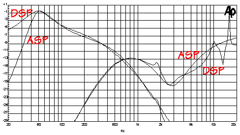
The high frequency variations are interesting though. As mentioned, none of it should be audible. But perhaps adding in some PEQ like one would use for speaker/room correction could muddle things up even more.

Unfortunately, even software like Roon can mess things up as demonstrated here.

I'd like to see the same filter set created in rePhase and implemented as FIR as a further comparison to the above for the hardware that can handle it.
 
OP
M

mdsimon2

Major Contributor
Forum Donor
Joined
Oct 20, 2020
Messages
2,515
Likes
3,369
Location
Detroit, MI
I think Camilla only does PEQ/biquad and that's how those filters were created?

Yes, in Camilla the filters are implemented using IIR, just like the miniDSP platforms. Camilla also has FIR capability and a RPi4 running Camilla can easily handle 100K+ taps per channel x 8 channels.

MiniDSP products have had sub/bass filter resolution problems for over a decade mostly because the hardware has limited processing power to resolve the quantity of filters needed and using biquads over PEQ is always recommend. For their hardware that can implement FIR they are very limited with the amount of taps available. In their own forums there are countless posts about sub bass optimization. I had a 4x10 in use for my active XO for nearly a decade and couldn't get the sub bass resolution I enjoy now using a computer.

This is an interesting point because I expected issues with the fixed point nanoDIGI as described in this thread -> https://www.minidsp.com/forum/software-support/2811-re-4x10-problems-in-low-frequency-ranges?start=0 so was surprised to see that the nanoDIGI was fine but the floating point SHARC's had issues. Although what I am doing from a low frequency EQ perspective is pretty mild which is why I assume I don't have the issues mentioned in that thread.

I'd like to see the same filter set created in rePhase and implemented as FIR as a further comparison to the above for the hardware that can handle it.

Good suggestion, I'll explore this, although the only thing I am confident that will be able to implement the low frequency stuff with FIR is Camilla. Another interesting thing to explore would be to switch to the 48 kHz plugins for the 2x4HD (DDRC-24) and the miniSHARC (4x8 and/or OpenDRC) and see if that changes anything.

Michael
 
OP
M

mdsimon2

Major Contributor
Forum Donor
Joined
Oct 20, 2020
Messages
2,515
Likes
3,369
Location
Detroit, MI
A nice learning from this effort is I thought I was closer to 0 dB on my low frequency EQ than the frequency sweeps actually show. As a result I increased the level of all channels by 2 dB on my LXmini system and Camilla has yet to report a clipped sample. Might even see if I can add more if I don't see any clipped samples after another week or so.

Michael
 

DWPress

Major Contributor
Forum Donor
Joined
May 30, 2018
Messages
1,023
Likes
1,473
Location
MI
Good suggestion, I'll explore this, although the only thing I am confident that will be able to implement the low frequency stuff with FIR is Camilla. Another interesting thing to explore would be to switch to the 48 kHz plugins for the 2x4HD (DDRC-24) and the miniSHARC (4x8 and/or OpenDRC) and see if that changes anything.

Awesome, if you do explore doing it in FIR and rePhase keep in mind linear vs minimum phase in creating the filter set.

It's been awhile since I played with the plugins but if I remember right using the 48kHz ones just allowed for more PEQ bands so not sure there would be any improvement, probably the contrary.
 

Rewind

Member
Joined
Sep 7, 2022
Messages
53
Likes
21
Now I have to learn Camilla. From what I read it is a bit more complicated than Minidsp.

This confirms my opinion of Minidsp. Sold my Minidsp 4x10HD and never looked back.

Doesn’t this problem become worse the more plugins you use? EQ, delay, FIR, etc. I remember form when I recorded songs in my bedroom studio, that after a few VST plugins, the sound quality deteriorated quite a lot. But in modern music, it is the way to go. Who can afford a Neve or an original Pultec and spend the time to route the signal through all those analog devices. You are probably already listening to the effects of all these plugins in the finished production.
 

Juhazi

Major Contributor
Joined
Sep 15, 2018
Messages
1,725
Likes
2,910
Location
Finland
Being long-time ueser of 4x10HD and 2x4HD (sharc) units, I'm interested in this issue...

From SL site

lxmini_asp_vs_dsp-c.jpg

This shows the net correction. But what is important is if bass correction has excessive positive gain. Basic guideline for digital eq is to suppress, not elevate to not introduce digital clipping of high level imput signals (what easily happens when measuring 0dB level signal).

A bit another issue that I have noticed here:
Here is analog output measurement of my Yamaha XCD-50 player (YPAO) with it's default Enhancer setting vs. pure. Low signal level. Even speaker response shows it!

Bt Enh On Off 50Hz disto-tile.jpgWXC-50 Enhancer on vs off distortion.jpg

Enhancer info.jpgEnhancer off Settings1.jpg
 
Last edited:

TNT

Active Member
Joined
Jun 24, 2020
Messages
244
Likes
157
It hasn't anything to do with which Sharc DSP (or any calculating HW for that matter) is used, this is in the software executed only...

I really find CamillaDSP excellent and truly completely transparent. Try it.

Tip: There are a lot of used Mac Minis on the market - get one, not older than 2014, with a SSD. Silent, sleek and perfect for the job. If you need more than one optical output for a multi way - get a RME Digiface - or a multichannel USB DAC.

//
 

xplo5iv

Member
Joined
Oct 28, 2021
Messages
16
Likes
8
Location
UK
It hasn't anything to do with which Sharc DSP (or any calculating HW for that matter) is used, this is in the software executed only...

I really find CamillaDSP excellent and truly completely transparent. Try it.

Tip: There are a lot of used Mac Minis on the market - get one, not older than 2014, with a SSD. Silent, sleek and perfect for the job. If you need more than one optical output for a multi way - get a RME Digiface - or a multichannel USB DAC.

//
Try reading the thread - OP has CamillaDSP as well, it's part of the discussion.
DSP Hardware does make a difference as different calculation methods are available on different hardware, and they therefore have different SINAD
That's not to say that SHARC isn't as good, it may just be the specific implementation
 

Marc v E

Major Contributor
Joined
Mar 9, 2021
Messages
1,106
Likes
1,607
Location
The Netherlands (Holland)
@mdsimon2 when I emailed minidsp support about the initial tests in the flex thread, their response was that the input signal was exceeding 0db and should never do so. Could that be the case here? I'm not 100% sure I read your graphs correctly. It basically implies that with , say +10 db applied for eq, the (test)signal should never exceed -10db if I understood correctly.
 

TNT

Active Member
Joined
Jun 24, 2020
Messages
244
Likes
157
...
DSP Hardware does make a difference as different calculation methods are available on different hardware, and they therefore have different SINAD
......
Read may answer again - I said it is not the HW, but the SW (i.e. algo.).

Why did you comment my post by repeating my message?

//
 
OP
M

mdsimon2

Major Contributor
Forum Donor
Joined
Oct 20, 2020
Messages
2,515
Likes
3,369
Location
Detroit, MI
@mdsimon2 when I emailed minidsp support about the initial tests in the flex thread, their response was that the input signal was exceeding 0db and should never do so. Could that be the case here? I'm not 100% sure I read your graphs correctly. It basically implies that with , say +10 db applied for eq, the (test)signal should never exceed -10db if I understood correctly.

These filters do not have any boosts above 0 dB. They are used with a downstream Okto dac8 pro for volume control so have level adjustments built in to ensure that the level never goes above 0 dB as I want to avoid digital clipping.

The first way to see this is in this measurement showing the filter frequency response.

1677425341935.png


The white line was created by running a frequency sweep with no filters applied at a generator level of -1 dBFS. As these measurements are purely digital you can see that we get back a flat response at the expected -1 dBFS. The frequency sweeps for the filters were also run at the same -1 dBFS generator level and you can see that in all cases the response is below the flat response indicating that there is no boost exceeding 0 dB.

This is also evident in the FFTs as these are reported in dBFS and not normalized to the fundamental. Looking at this measurement for example.

1677425510697.png


Base: Input RMS -1.03 dBFS, THD: -147.7 dB based on 49 harmonics [20..22000 Hz], N: -127.5 dB [20..22000 Hz], THD+N: -127.5 dB [20..22000 Hz]
Low: Input RMS -5.39 dBFS, THD: -144.9 dB based on 49 harmonics [20..22000 Hz], N: -103.0 dB [20..22000 Hz], THD+N: -103.0 dB [20..22000 Hz]

Playing a 100 Hz tone at -1 dB results in a captured level of -1.03 dBFS for the flat response and -5.39 dBFS for the low filter response. This is expected based on the frequency response graph. So here you have a lower input level after the filter is applied but this results in a higher noise floor.

But yes in any DSP system you want to make sure that your combination of input signal + channel routing + filters + volume control (if doing volume control in the DSP) does not exceed 0 dB at the output as this will result in a digital clipping.

Michael
 
Last edited:
OP
M

mdsimon2

Major Contributor
Forum Donor
Joined
Oct 20, 2020
Messages
2,515
Likes
3,369
Location
Detroit, MI
It hasn't anything to do with which Sharc DSP (or any calculating HW for that matter) is used, this is in the software executed only...

I am not sure I understand this claim. These measurements have three hardware DSPs (miniSHARC, 2x4HD, nanoDIGI). The SHARC based ones (miniSHARC and 2x4HD) show an elevated low frequency noise floor when low frequency filters are applied, the ADAU based one (nanoDIGI) does not show this.

That makes me feel like there is a potentially a hardware specific issue at play (or at least a specific implementation related to that hardware).

Michael
 
Last edited:

Marc v E

Major Contributor
Joined
Mar 9, 2021
Messages
1,106
Likes
1,607
Location
The Netherlands (Holland)
These filters do not have any boosts above 0 dB. They are used with a downstream Okto dac8 pro for volume control so have level adjustments built in to ensure that the level never goes above 0 dB as I want to avoid digital clipping.

The first way to see this is in this measurement showing the filter frequency response.

View attachment 267679

The white line was created by running a frequency sweep at a generator level of -1 dBFS. As these measurements are purely digital you can see that we get back a flat response at the expected -1 dBFS. The frequency sweeps for the filters were also run at the same -1 dBFS generator level and you can see that in all cases the response is below the flat response indicating that there is no boost exceeding 0 dB.

This is also evident in the FFTs as these are reported in dBFS and not normalized to the fundamental. Looking at this measurement for example.

View attachment 267680

Base: Input RMS -1.03 dBFS, THD: -147.7 dB based on 49 harmonics [20..22000 Hz], N: -127.5 dB [20..22000 Hz], THD+N: -127.5 dB [20..22000 Hz]
Low: Input RMS -5.39 dBFS, THD: -144.9 dB based on 49 harmonics [20..22000 Hz], N: -103.0 dB [20..22000 Hz], THD+N: -103.0 dB [20..22000 Hz]

Playing a 100 Hz tone at -1 dB results in a captured level of -1.03 dBFS for the flat response and -5.39 dBFS for the low filter response. This is expected based on the frequency response graph. So here you have a lower input level resulting in a higher noise floor.

But yes in any DSP system you want to make sure that your combination of input signal + channel routing + filters + volume control (if doing volume control in the DSP) does not exceed 0 dB at the output as this will result in a digital clipping.

Michael
So, if I understand correctly, the effect of an applied eq in a sharc dsp based device seems to be a higher noise floor: -120db, mostly in the lower regions.
 

HarmonicTHD

Major Contributor
Joined
Mar 18, 2022
Messages
3,326
Likes
4,835
These filters do not have any boosts above 0 dB. They are used with a downstream Okto dac8 pro for volume control so have level adjustments built in to ensure that the level never goes above 0 dB as I want to avoid digital clipping.

The first way to see this is in this measurement showing the filter frequency response.

View attachment 267679

The white line was created by running a frequency sweep at a generator level of -1 dBFS. As these measurements are purely digital you can see that we get back a flat response at the expected -1 dBFS. The frequency sweeps for the filters were also run at the same -1 dBFS generator level and you can see that in all cases the response is below the flat response indicating that there is no boost exceeding 0 dB.

This is also evident in the FFTs as these are reported in dBFS and not normalized to the fundamental. Looking at this measurement for example.

View attachment 267680

Base: Input RMS -1.03 dBFS, THD: -147.7 dB based on 49 harmonics [20..22000 Hz], N: -127.5 dB [20..22000 Hz], THD+N: -127.5 dB [20..22000 Hz]
Low: Input RMS -5.39 dBFS, THD: -144.9 dB based on 49 harmonics [20..22000 Hz], N: -103.0 dB [20..22000 Hz], THD+N: -103.0 dB [20..22000 Hz]

Playing a 100 Hz tone at -1 dB results in a captured level of -1.03 dBFS for the flat response and -5.39 dBFS for the low filter response. This is expected based on the frequency response graph. So here you have a lower input level resulting in a higher noise floor.

But yes in any DSP system you want to make sure that your combination of input signal + channel routing + filters + volume control (if doing volume control in the DSP) does not exceed 0 dB at the output as this will result in a digital clipping.

Michael
…. plus, I presume, one would also observe an increase in THD at higher frequencies as well if you were clipping (and not only at lower frequencies, as in the example in your post)
 
OP
M

mdsimon2

Major Contributor
Forum Donor
Joined
Oct 20, 2020
Messages
2,515
Likes
3,369
Location
Detroit, MI
So, if I understand correctly, the effect of an applied eq seems to be a higher noise floor: -120db, mostly in the lower regions.

You cannot read the noise floor directly off of the FFT due to FFT gain. Look at the summaries below the FFTs or the stepped sine sweeps to see the actual noise value. For example looking at the miniSHARC low filter at 100 Hz which is one of the worst ones.

1677426323361.png


Base: Input RMS -1.03 dBFS, THD: -147.7 dB based on 49 harmonics [20..22000 Hz], N: -127.5 dB [20..22000 Hz], THD+N: -127.5 dB [20..22000 Hz]
Low: Input RMS -5.39 dBFS, THD: -144.9 dB based on 49 harmonics [20..22000 Hz], N: -103.0 dB [20..22000 Hz], THD+N: -103.0 dB [20..22000 Hz]

Noise floor relative to the fundamental is -103 dB and at an absolute level is -5.4 - 103 = -108.4 dB, this is why I say it still clears 16 bit fidelity.

You can also see this in the stepped sine sweep.

1677426433909.png


The end of the sweep is -1 dBFS generator level which results in a capture level of between -5 and -6 dBFS. At this level the relative noise floor is between -100 and -105 dBr as shown in the FFT summary.

And looking at it in an absolute scale.

1677426512998.png


End of the sweep is giving an absolute noise level of around -108 dBFS which corresponds to a generator level of -1 dBFS.

Hope this helps.

Michael
 
OP
M

mdsimon2

Major Contributor
Forum Donor
Joined
Oct 20, 2020
Messages
2,515
Likes
3,369
Location
Detroit, MI
…. plus, I presume, one would also observe an increase in THD at higher frequencies as well if you were clipping (and not only at lower frequencies, as in the example in your post)

Yes, exactly. For those that have not seen what clipping looks like on a FFT this is what happens if I remove the level adjustment on the sub filter and send a 30 Hz tone at -1 dBFS. It's pretty obvious by the large amount of harmonics and reported input level above 0 dBFS.

1677426853845.png


Michael
 
Last edited:

Marc v E

Major Contributor
Joined
Mar 9, 2021
Messages
1,106
Likes
1,607
Location
The Netherlands (Holland)
I am not sure I understand this claim. These measurements have three hardware DSPs (miniSHARC, 2x4HD, nanoDIGI). The SHARC based ones (miniSHARC and 2x4HD) show an elevated low frequency noise floor when low frequency filters are applied, the ADAU based one (nanoDIGI) does not show this.

That makes me feel like there is a potentially a hardware specific issue at play (or at least a specific implementation related to that hardware).

Michael
There is one way to make sure this is software or hardware based. Use a minidsp with Dirac software. Not 100% reliable, but should at least give slightly different results if the root cause is software. If you plot the results in a graph the difference should be visible.
 

DWPress

Major Contributor
Forum Donor
Joined
May 30, 2018
Messages
1,023
Likes
1,473
Location
MI
Pretty sure it's the hardware limitation, even miniDSP admits as much and is the reason why you have limited filter taps or PEQ bands per channel. With a modest computer like a RPi or a tiny Windows box with a Celeron processor like Archimago demonstrates here you can do so much more.
 
Top Bottom