• WANTED: Happy members who like to discuss audio and other topics related to our interest. Desire to learn and share knowledge of science required. There are many reviews of audio hardware and expert members to help answer your questions. Click here to have your audio equipment measured for free!

DIY Audio switch for home automation

headshake

Active Member
Joined
Apr 20, 2019
Messages
297
Likes
238

Weeb Labs

Addicted to Fun and Learning
Joined
Jun 24, 2020
Messages
608
Likes
1,426
Location
Ireland
Yes, HASS integration is what I'm looking for.
I've different options:
1. ESP-01S + relay board
2. use the GPIO of the raspberry Pi that I'm using as streamer to control a relay board, using the HA integration for remote raspberry PI
3. use the GPIO of the raspberry Pi that I'm using as streamer to control a relay board, using the moode GPIO automations (no integration with HA)
4. use a 12V trigger (no integration with HA)

I would like also to control the Benchmark DAC input selection. The only external method is to use an IR blaster (eg Broadlink RM).
I would suggest the 01S route. It's a very compact board and you should have adequate GPIO for both the IR emitter and relay.
 

dualazmak

Major Contributor
Forum Donor
Joined
Feb 29, 2020
Messages
2,850
Likes
3,047
Location
Ichihara City, Chiba Prefecture, Japan
Although belated, just for your reference, let me share about professionally built SP-level and Line-level manual(!) selectors with non-magnetizable parts including nice durable rotary switches. Hope your web browser would properly translate these pages into English.

https://audiodesign.co.jp/

SP selectors;
https://audiodesign.co.jp/HAS/HAS-3S.html

AMP + SP selectors;
https://audiodesign.co.jp/HAS/HAS-33S.html

Line selectors;
https://audiodesign.co.jp/HAS/HAS-3L.html

Balance Line selectors;
https://audiodesign.co.jp/HAS/HAS-3LB.html

Dual Line selectors;
https://audiodesign.co.jp/HAS/HAS-33L.html
 
Last edited:

dualazmak

Major Contributor
Forum Donor
Joined
Feb 29, 2020
Messages
2,850
Likes
3,047
Location
Ichihara City, Chiba Prefecture, Japan
Further important references;
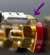
As @Buckeye Amps mentioned, the board designer and I have been going at this diagnosis feverishly. Admittedly, should have found sooner, but I made a critical test error and (as mentioned) the designer had been plagued by a bad dummy load that obscured his measurements until just recently. Since I have been working closely on the troubleshooting, Dylan is allowing me to represent the team to share our finding. In the end, the designer found the cause.

And the culprit is...

1675820279181.png

The binding post connection tab. :mad:
Click to expand...

Let me again share my similar experiences on this issue.

I Have written/shared the similar topics here (post #250 on my project thread) and here (post #13 on the remote thread) for SP high-level cable wiring/connectors. Recently, I also touched on the same topics here and here.

Here, I wrote;
If you take a look inside some rather high-end HiFi amplifiers, you'll see that the SP output wiring (and power wiring?) uses non-magnetic terminals and screws made of brass (no iron at all) or pure copper. However, this is also a common-sense measure to prevent sound quality deterioration in HiFi amplifiers. I remember it being pointed out and explained in interviews with a Yamaha amplifier designer and a Rotel engineer.

It is frustrating when working with magnetized screwdrivers because you can't catch the screws, though.

Yamaha's and Rotel's amplifier designers had a hard time persuading the assembly workers at the amplifier factories, but in the end they convinced them to use non-magnetic terminals and screws, giving priority to sound quality; I've also heard that the screwdriver, which uses a chuck to fix screws and bolts to the tip, was devised so that it could be used in factories.


In my DIY audio setup, I have the same thing; I strictly/completely eliminate/avoid any magnetizable metal/screw in my SP cabling/connecting.


Buckeye Amps decided replacement of their iron parts of "the issue" by brass one accordingly; please refer to here and here.
 

venquessa

Member
Joined
Feb 6, 2023
Messages
59
Likes
66
In terms of home automation devices you could use for this, without any electronics required....

SOnOff LV.

It's a pre-canned low voltage Wifi switch. ESP8285, supports Tasmota firmware so integrations with the usual stuff the usual ways. The relay is "dry contact" of course. The idea would be to use that one relay to flip your other relays.

In terms of the debate around magnetic fields. The magnetic field is 'static' if we consider the power rail noise as negligible. However. Faraday said a changing current induces a magnetic field around a conductor. Also, that a changing magnetic field induces a current in a conductor. So the magnetic field will be influenced by the changing current of the AC signal line. That said however. If it is a signal line, it will be going between IO ports with 10KOhm or higher impedance. There won't be much current at all. A 1V peak on a line level going into 10KOhm results in 0.0001 amps. 1/10th of a milliamp. However, the relay coil impedance is far far lower than that and will be consuming 10s of mlliamps. I'd suggest if you can measure that, grand, I doubt you'll hear it.

A few tips though.

1. Use "normally closed" relays (or the NC pole) will moot the whole point. The relay "in use" will be OFF when active and the coil field in it will be neutral.
2. Be careful of the relay coil inductive pulse. Make sure your relay board has a flyback/free wheel diode. There would be interesting debate on what effect the collapsing of the inductor magnetic field and it's effect on the audio signal. Although only relevant for the outputs feeding an amp. When you disconnect an input, or discharge the coil in the relay there will be an EMF pulse as the current races (free wheels) backward around the diode. It shouldn't ring for very long, depends on the capacitance of the circuit etc. etc.

What about SSRs?
 

venquessa

Member
Joined
Feb 6, 2023
Messages
59
Likes
66
2 further options.

Don't switch, mix. A few opamps in mix + a final invertor to correct phase. Then use electronic potentiometers and control them IoT style.

Or do it digitally like I am. All digital in to one place. Mix them all into a couple of streams and send those to different outputs. The 'selection and volume' is done in software. Easy enough to automate it.
 
Top Bottom