• WANTED: Happy members who like to discuss audio and other topics related to our interest. Desire to learn and share knowledge of science required. There are many reviews of audio hardware and expert members to help answer your questions. Click here to have your audio equipment measured for free!

DC blocking capacitors audibility.

Roland68

Major Contributor
Joined
Jan 31, 2020
Messages
1,464
Likes
1,284
Location
Cologne, Germany
Its TI, wheres there measurements to explain what they "heard"?
TI just has the same access to measuring devices as everyone else. That's why they can't measure more or anything different than everyone else.
If it were possible to measure these aspects and publish metrics on them, they would definitely do it and avoid these very complex, difficult and expensive human tests.
 

Cbdb2

Major Contributor
Joined
Sep 8, 2019
Messages
1,565
Likes
1,549
Location
Vancouver
The reason why would be the input sensitivity is high enough to pick up interference from the capacitor plate as it turns itself into an antenna. Most chip amps that have this issue would always land a small value cap in parallel with a high ohm resistor to ground on each signal in out to snub this RF. Sometimes, putting a 1-3 pF cap across signal + and signal - is all you really need in a fully balanced circuit to snub the RF from coupling caps, because the common mode rejection effect the circuit would impose, would take care of the rest.

But capacitors induce distortion within the audio range as well. Especially if they are blocking voltages several times larger than the signal. This is caused by the magnetic field effects of its construction imposing changes in the circuit. A prime example of this would be using a WHIMA MKP cap that has excessive fields and a horrible coupling device in tube amps compared to a Solen or Jupiter non-metallized wound film and foil type.

Differently constructed caps have different distortion profiles and when you select one for coupling use you use the type and size in the circuit that is less sensitive to add its noise profile to the signal.
A DC voltage across a cap produces zero magnetic field. And the electric field stays almost entirely in the cap.
 

Cbdb2

Major Contributor
Joined
Sep 8, 2019
Messages
1,565
Likes
1,549
Location
Vancouver
Next time try bigger caps. Douglas Self published distortion measurements of el- and film caps, and while the film caps were good the elcaps had significant distortion rising with voltage across them. To get rid of distortion one needs to select them so large that the voltage across them is not higher than 80 mv at 20 Hz.
To clarify, thats AC voltage, the DC or bias across the cap dosnt matter.
 

nutzandvoltz

Member
Joined
Oct 14, 2023
Messages
48
Likes
18
A DC voltage across a cap produces zero magnetic field. And the electric field stays almost entirely in the cap.

On the contrary, stray magnetic fields are always part of real world models of capacitors. Because it has to do with the construction.

An example:

Magnetic Field from a Charging Capacitor​


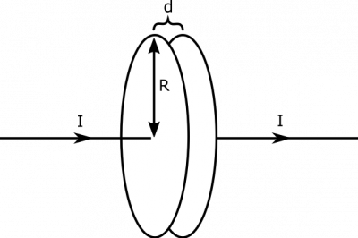
Suppose you have a parallel plate capacitor that is charging with a current I=3 A
. The plates are circular, with radius R=10 m and a distance d=1 cm
apart. What is the magnetic field in the plane parallel to but in between the plates?


Charging Capacitors

Facts​


  • The capacitor is a parallel plate capacitor with circular plates.
  • R=10 m

  • d=1 cm

  • The capacitor is charging with a current I=3 A
  • .

Lacking​


  • A description of the magnetic field.

Approximations & Assumptions​


  • We are only concerned about a snapshot in time, so the current is I
  • , even though this may change at a later time as the capacitor charges.
  • The electric field between the plates is the same as the electric field between infinite plates (we'll ignore the electric field at the edges of the capacitor): This allows us to assume the electric field is constant between the plates. This is a good assumption with two big plates that are very close together.
  • The electric field outside the plates is zero: This also ties back to having two big plates separated by a small distance. Making this assumption allows us to simplify down our equations when calculating the flux through our surface.

Representations​


  • We represent the electric field in a parallel plate capacitor as
    E⃗ =Q/Aϵ0x^
where Q is the charge on a plate, A is the area of the plate, and x^
  • is directed from one plate to the other.
  • We can represent the magnetic field from a changing electric field as


∫B⃗ ∙dl⃗ =μ0Ienc+μ0ϵ0dΦEdt


  • We represent the situation with the following visual:


Plane in which we wish to find B-field

Solution​


We wish to find the magnetic field in the plane we've shown in the representations. We know from the notes that a changing electric field should create a curly magnetic field. Since the capacitor plates are charging, the electric field between the two plates will be increasing and thus create a curly magnetic field. We will think about two cases: one that looks at the magnetic field inside the capacitor and one that looks at the magnetic field outside the capacitor.
Due to the circular symmetry of the problem, we choose a circular loop in which to situate our integral ∫B⃗ ∙dl⃗
. We also choose for the loop to be the perimeter of a flat surface, so that the entire thing lies in the plane of interest, and there is no enclosed current (so Ienc=0
- there is only the changing electric field). We show the drawn loop below, split into two cases on the radius of the loop.
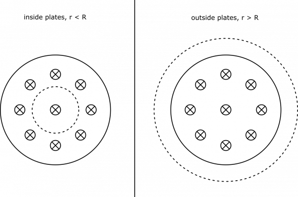


Circular Loops

Below, we also draw the direction of the magnetic field along the loops. We know the magnetic field is directed along our circular loop (since the changing electric flux creates a curly magnetic field) – if it pointed in or out a little bit, we may be able to conceive of the closed surface with magnetic flux through it, which would imply the existence of a magnetic monopole. This cannot be the case! We also know that the field is directed counterclockwise, due to the increasing electric field into the page. (This comes from an extension of Lenz's Law, but will not needed for this course).


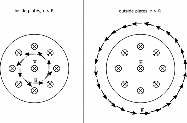
Circular Loops, with B-field shown

We are pretty well set up to simplify our calculation of the integral in the representations, since the B-field is parallel to the loop's perimeter. Below, we show the integral calculation, where the magnetic field at a radius r

is displayed as B(r)
.


∫B⃗ ∙dl⃗ =∫B(r)dl=B(r)∫dl=2πrB(r)


Next, we need to find the changing electric flux in our loop. Since our loop was described with a flat surface, and the electric field is directed parallel to the area-vector of the loop, we can write electric flux as ΦE=E⃗ ∙A⃗ =EA

. This formula will need to be split up for parts of the surface inside the plates versus outside, since the electric field is different.


ΦE, in=EA=Q/Aplateϵ0Aloop=Qϵ0πR2πr2=Qr2ϵ0R2


ΦE, out=EA=EinAin+EoutAout=Q/Aplateϵ0Aplate+0=Qϵ0πR2πR2=Qϵ0


Now, if we wish the find the change in flux, we will take a time derivative. Notice that all the terms in the flux expressions above are constant, except for Q

, which is changing with time as dictated by I
.


dΦEdt=dQdtr2ϵ0R2=Ir2ϵ0R2, inside, r<R


dΦEdt=dQdtϵ0=Iϵ0, outside, r>R


We can now connect the pieces together (remember, Ienc=0

, so we omit it below). We can write:


2πrB(r)=∫B⃗ ∙dl⃗ =μ0ϵ0dΦEdt=μ0Ir2R2, inside, r<R


2πrB(r)=∫B⃗ ∙dl⃗ =μ0ϵ0dΦEdt=μ0I, outside, r>R


We are ready to write out the magnetic field.


B(r)=⎧⎩⎨μ0Ir2πR2μ0I2πrr<Rr>R


Notice, the distance between the plates has no effect on the magnetic field calculation. Also, the amount of the charge on the plates at a given time does not matter – we only care about how fast the charge is changing (the current!). Also, it is interesting that outside the plates, the magnetic field is the same as it would be for a long wire. This would be just as if the capacitor were not there, and the wire were connected. Below, we show a graph of the magnetic field strength as a function of the distance from the center of the capacitor.


B-Field Strength, Graphed

We have enough information to find the maximum B-field, which is at the edge of the plates:

Bmax=μ0I2πR=4π⋅10−7Tm/A⋅3 A2π⋅10 m=60 nT


Of course we can look at a research paper about a particular type as well: https://www.researchgate.net/figure...citors-fabricated-from-polymer_fig4_224750062
 

egellings

Major Contributor
Joined
Feb 6, 2020
Messages
4,114
Likes
3,356
In short, a static electric charge does not have a magnetic field around it; when the charge moves, then a magnetic field forms around the flow path.
 

Cbdb2

Major Contributor
Joined
Sep 8, 2019
Messages
1,565
Likes
1,549
Location
Vancouver
Beat me to it. At nutzandvoltz. From your post: "We wish to find the magnetic field in the plane we've shown in the representations. We know from the notes that a changing electric field should create a curly magnetic field. Since the capacitor plates are charging, the electric field between the two plates will be increasing and thus create a curly magnetic field." or Faradays law.
So no changing electric field (like a charged cap) no magnetic field.
The mag field comes from the current. Amperes law. A charged cap has no current thru it so no magnetic field.
This is basic electromag theory.
When you put a AC voltage (signal) across the cap you get AC current and a mag field. Outside the cap the mag field is the same as if the cap was replaced by a straight wire, so the cap does not change the mag field around it, or in other words the mag field is the same with or without the cap even with AC across it.
So your theory is completely wrong.
 

nutzandvoltz

Member
Joined
Oct 14, 2023
Messages
48
Likes
18
Beat me to it. At nutzandvoltz. From your post: "We wish to find the magnetic field in the plane we've shown in the representations. We know from the notes that a changing electric field should create a curly magnetic field. Since the capacitor plates are charging, the electric field between the two plates will be increasing and thus create a curly magnetic field." or Faradays law.
So no changing electric field (like a charged cap) no magnetic field.
The mag field comes from the current. Amperes law. A charged cap has no current thru it so no magnetic field.
This is basic electromag theory.
When you put a AC voltage (signal) across the cap you get AC current and a mag field. Outside the cap the mag field is the same as if the cap was replaced by a straight wire, so the cap does not change the mag field around it, or in other words the mag field is the same with or without the cap even with AC across it.
So your theory is completely wrong.


construction internally causes changes, and not observed outside and will appear the same.
The way the plates are wound for the package can vary the micro inductance, that cancels itself out across the dielectric layer with the opposing plate that is in opposite charge and flux state. This on itself will cancel magnetic radiation exiting outside of the cap. Materials used are chosen so that they don't posses much of this phenomenon.All modern capacitors (whether plastic or electrolytic) have series inductance of between 0.500 nH and 100 nH so their impedance becomes inductive as frequency rises.

And you will find parts that work well in one circuit, but perform miserably in another even though the electronic parameters are the same, and this is due to materials used and construction technique.

But construction techniques have the same distortion profile as well, and gets better or worse with what type of materials used and what kind of circuit it is applied in.
 

dualazmak

Major Contributor
Forum Donor
Joined
Feb 29, 2020
Messages
2,877
Likes
3,100
Location
Ichihara City, Chiba Prefecture, Japan
Although quite be lated, I just came across with this thread.

Jus for your possible interest and reference, I intensively measured Fq response of my SP-out-level signals before and after the protection capacitors for my midrange squawker, tweeter and supertweeter (ref. here and here).
 

Cbdb2

Major Contributor
Joined
Sep 8, 2019
Messages
1,565
Likes
1,549
Location
Vancouver
A DC voltage across a cap produces zero magnetic field. And the electric field stays almost entirely in the cap.
You said:
On the contrary, stray magnetic fields are always part of real world models of capacitors. Because it has to do with the construction.

So you were totally wrong there but you have to keep going.

construction internally causes changes, and not observed outside and will appear the same.
The way the plates are wound for the package can vary the micro inductance, that cancels itself out across the dielectric layer with the opposing plate that is in opposite charge and flux state. This on itself will cancel magnetic radiation exiting outside of the cap. Materials used are chosen so that they don't posses much of this phenomenon.All modern capacitors (whether plastic or electrolytic) have series inductance of between 0.500 nH and 100 nH so their impedance becomes inductive as frequency rises.

And you will find parts that work well in one circuit, but perform miserably in another even though the electronic parameters are the same, and this is due to materials used and construction technique.

But construction techniques have the same distortion profile as well, and gets better or worse with what type of materials used and what kind of circuit it is applied in.
If ALL the electronic parameters are the same they will perform exactly the same. Or using a electronics simulator would be worthless. Construction and material are what give all components there electrical parameters.
And anything that runs current has inductance.
 

nutzandvoltz

Member
Joined
Oct 14, 2023
Messages
48
Likes
18
You said:
On the contrary, stray magnetic fields are always part of real world models of capacitors. Because it has to do with the construction.

So you were totally wrong there but you have to keep going.


If ALL the electronic parameters are the same they will perform exactly the same. Or using a electronics simulator would be worthless. Construction and material are what give all components there electrical parameters.
And anything that runs current has inductance.
Difference is I'm right, and its apparent you don't understand construction of parts impart small characteristics beyond its general parameters it serves and this can be problematic.
 

SIY

Grand Contributor
Technical Expert
Joined
Apr 6, 2018
Messages
10,564
Likes
25,433
Location
Alfred, NY
Difference is I'm right
Except measurements show you're not (example, example, example, example), with one exception- large film caps can pick up a bit more stray hum than small electrolytics. Beyond that... no.

When experiment contradicts your hypothesis, give up the hypothesis, don't just wave your hands faster.
 

nutzandvoltz

Member
Joined
Oct 14, 2023
Messages
48
Likes
18
Except measurements show you're not (example, example, example, example), with one exception- large film caps can pick up a bit more stray hum than small electrolytics. Beyond that... no.

When experiment contradicts your hypothesis, give up the hypothesis, don't just wave your hands faster.
But what I say is not a theory nor a hypothosis. I'm just dragging up what others came to conclusion lately, now, I'm going to find the contrary out there that is known. I know certain parts have certain types of distortion or would induce distortion in a circuit because of its construction.
So far they only go into saying the magnetic field doesn't leave the part. Because the magnetic flux field is low. But they don't get into the higher frequencies either. Where the part starts imparting these stray parameters.


It also will come across certain people when they go to make their circuit they simulated and it does not perform well.
But things like this are because real world components will be different than ideal models.
 
Last edited:

nutzandvoltz

Member
Joined
Oct 14, 2023
Messages
48
Likes
18
@SIY Basically, the RF based anomalies with parts have been a place where the electronics math breaks and only can prove the basic physics of the device.

Just like intrinsic resistance in transistors that academia gave up on how to come up with a calculation. That is why they have that ridiculous 'transistor man' model currently.
 

nutzandvoltz

Member
Joined
Oct 14, 2023
Messages
48
Likes
18
Until you have data, that’s exactly what it is.
Such in doubt. I have to guess there isn't many people on the forum that went to electronics school. Nor some that got into researching micro-anomalies with parts. I find that the info on a lot of electronic subjects have been streamlined on the internet compared to my college text books that were written 30+ years ago.

So is this what people do now these days instead of talking about a subject : Find an argument that supports theirs, or find someone's research, and not questioning it nor discussion, just accepting one and discounting others or just blatantly assume and voice that they are wrong. I am a scientist of electronics, so I am always trying to find answer, in a construct of very few physical laws compared to its theories and always question and look for topics that should be a discussion instead of settling on one or another person's findings.

Can anyone explain the noise generated in the regulator circuit mathematically that is caused by using a ceramic bypass cap compared to a MLCC type cap used in the same place?
I doubt it because no one has figured out how to apply a math formula to it. Just observed the phenomenon.
 

Cbdb2

Major Contributor
Joined
Sep 8, 2019
Messages
1,565
Likes
1,549
Location
Vancouver
@SIY Basically, the RF based anomalies with parts have been a place where the electronics math breaks and only can prove the basic physics of the device.

Just like intrinsic resistance in transistors that academia gave up on how to come up with a calculation. That is why they have that ridiculous 'transistor man' model currently.
Show me where "the math (Maxwells equations) breaks down". Which intrinsic resistance, I remember there where quite accurate equations for these. I had to Google the transistor man model. Its a way to explain transistors to children. Engineers use the model developed in the first chapter of this 40 year old book.


Cbdb2

Major Contributor
Joined
Sep 8, 2019
Messages
1,565
Likes
1,549
Location
Vancouver
Difference is I'm right, and its apparent you don't understand construction of parts impart small characteristics beyond its general parameters it serves and this can be problematic.
Sure just like you were right about stray magnetic fields from a cap, wait you were totally wrong. If you even read those electronics books from 30years ago you seem to have forgotten most if it.
 
Top Bottom