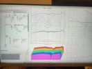
The resistor in the woofer circuit damps the "knee" that can happen sometimes on woofer crossovers and reduces some output bump we would get in the summing around the woofer to mid crossover point. This is a fairly common practice in woofer circuits since you get this benefit and it can also sometimes help align the phase a bit better if needed.
The bypass cap is a notch circuit for the mid. The mid has a little bit of cone breakup, which doesn't impact the distortion but was not as low in output as we wanted with the second order filter. This help notch out the peak and provide a better overall rolloff for the mid.
Thanks for sharing the added clarifications. I have quoted my use of the word unusual as bypass caps are fairly common but are used for different reasons. Agree your crossover uses one purposefully whereas others use them for more questionable reasons. Have not seen the woofer resistor damper previously, so a novice would be even less likely to have encountered.
If a novice looks in the VituixCAD library, they can readily find the circuits for various filter topologies, notch filters or a passive L-Pad (as used in your tweeter circuit). They will not find when a bypass cap might help as a notch and would more likely add more components to construct a more typical notch filter. So would consider it a more advanced application despite its simplicity.
Find it refreshing that CSS is willing to openly publish and discuss your crossover designs. It does help beginners and encourage others to improve. It is much more in the spirit of DIY than others selling kits generally provide. 

